In this exercise, you will reset the corridor targets, rebuild the corridor, and then examine how the conditional subassembly affects the corridor model.
This exercise continues from Exercise 3: Adjusting Conditional Subassembly Properties.
Set targets and rebuild the corridor
- Open Assembly-2c.dwg, which is available in the tutorials drawings folder.
The drawing contains the corridor assembly that you designed in the previous three exercises.
- In the drawing, click the Corridor - (1) corridor.
- Click tab
 panel
panel  drop-down
 .
. - In the Corridor Properties dialog box, on the Parameters tab, click Set All Targets.
- In the Target Mapping dialog box, in the Object Name column, click <Click Here To Set All>.
- In the Pick A Surface dialog box, click Existing Ground.
- Click OK three times to close the dialog boxes and rebuild the corridor.
Examine the rebuilt corridor
- In the View/Edit Corridor Section Tools toolbar, click
 to return to station 0+00.
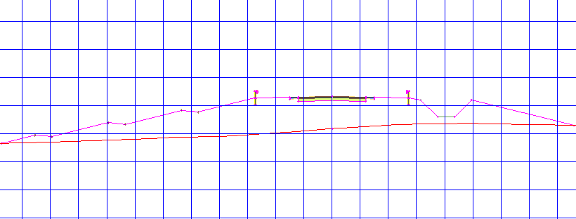
 At the first few stations, the corridor is in a relatively deep fill condition. In Exercise 2: Adding Conditional Subassemblies to a Corridor Assembly, you attached the DaylightBench subassembly to the Fill 5.00: 10000.00 conditional subassembly. The fill condition at this station is greater than 5.0001’, so the DaylightBench subassembly is applied.

- Click
 eight times to advance to station 2+00.
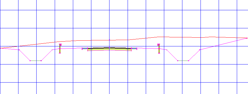
 Starting at station 2+00, the corridor enters a cut condition. At this station, the cut is less than 5.0000’, so the DaylightOffsetToSurface subassembly is applied after the ditch.

- Click
 again.
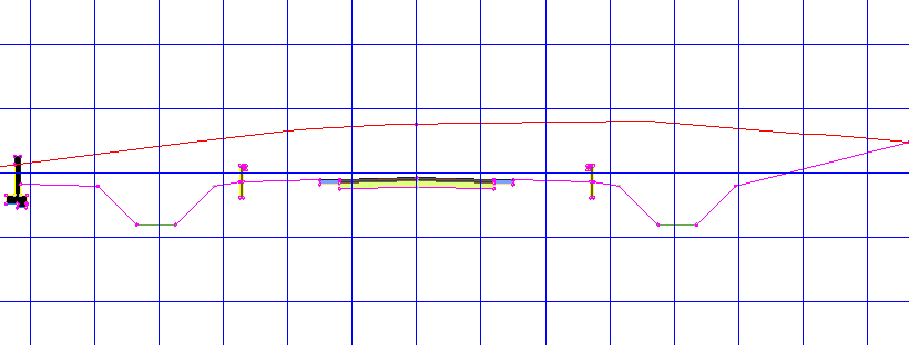
 Starting at station 2+25, the cut condition is greater than 5.0001’. As you specified, the DaylightWidthSlope and RetainWallVertical subassemblies are applied after the ditch.

- Continue using the


 buttons to examine the cut and fill conditions along the corridor.
Further exploration: Apply what you learned to the right-hand side of the corridor assembly. Use different combinations of daylight subassemblies with the ConditionalCutOrFill subassembly and examine the results.
To continue to the next tutorial, go to Saving and Sharing Corridor Assemblies.