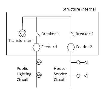
You can create a separate drawing to contain a internal view of a structure. For example, you might have a substation where a conductor in a segment is connected to an internal device (transformer/breaker/fuse). The internal devices are connected to each other with a conductor.

Before creating structure internal views, set the display model for the structure internal drawing and specify the size of the structure internal bounding box. See Set Electric Options.
If you use the Electric Explorer to insert a device where a device is already located, you are prompted to insert a structure and the devices are moved to the structure internal. If there is more than one structure at the location, you are prompted to specify the structure to which to associate the structure internal view. For more information about structure internals, see Create Structure Internal Views.
- Define and save two display models, one for the main .dwg and one for the structure internal view .dwg.
- Click Home tab
 Display panel
  Display Model list. Select the display model for the main .dwg.
 - Click Home tab
 Display panel
  Generate Graphic.
 - In the main .dwg, create a structural feature to associate with the geometry in the internal view.
- Draw the feature with which to associate the internal view. For example, a substation.
- In the Structure container, select the new substation and click More
 Structure Internal.
 A second .dwg is created for the structure internal.
- In the structure internal .dwg, zoom to view the structure internal area.
For example, perform a Zoom Center using the center point of the structure internal drawing.
You can adjust the size of this area in Document Options. For more information, see Set Electric Options.
- Optionally, select the Structure Internal profile to display feature containers relevant to creating a structure internal.
- In the structure internal .dwg, draw the internal features, for example, conductors and devices. Tip: Start with a conductor that has a specific length (for example, 3 meters). If you start digitizing without a value you might create a conductor with a size that is inappropriate to the device you create later.
- To create a connection between a feature in the structure internal and a feature on the map, use the following procedure:
- In the Electric Explorer, select the feature that you want to associate with a feature in the structure internal .dwg.
For example, in the Conductor container, select a conductor. Use Select From Map
 or Select From Trace
 to populate the feature container with the correct feature. You can then select this feature in the feature container. Note:
The external feature (for example, conductor) must geometrically touch the structure containing the internal features.
- In the Electric Explorer, select the internal feature that you want to associate with a feature in the external .dwg.
For example, in the Conductor container, select a conductor and in the Device container, select a structure internal device. Use Select From Map
 or Select From Trace
 to populate the feature container with the correct feature. You can then select this feature in the feature container.
 - In the Conductor container, click More
 Connect With Internal Device.
 Alternatively, in the Device container, click More
 Connect With External Conductor. You can also use drag and drop to make the connection.
 A logical connection is made between the external and internal features.
The structure internal device is displayed in the Structure container in the Electric Explorer. A special icon indicates that the structure has an internal view.
- In the Electric Explorer, select the feature that you want to associate with a feature in the structure internal .dwg.