PolyToolsModeling : GlobalUtilityPlugin
The PolyToolsModeling Global Utility Plugin introduced in 3ds Max 2011 exposes an interface that provides MAXScript access to the Graphite Modeling tools.
The functionality was first implemented in 3ds Max 2010 using different functions that were not officially supported as MAXScript tools. This interface consolidates all relevant properties and methods, and lets MAXScript users apply them in their own tools.
PolyToolsModeling interfaces:
Loops Panel
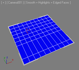
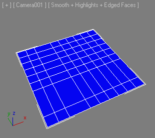
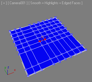
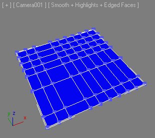
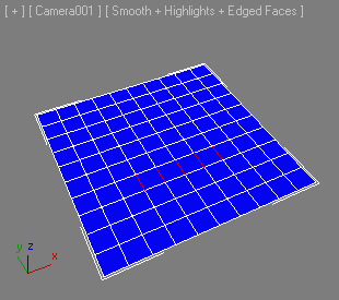
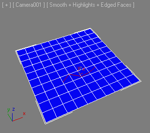
Creates connections between sub-object elements across distance and other topology.
Removes a loop in the current sub-object level and automatically removes any left over vertices.
Automatically fits selected edges or vertices to the surrounding flow of the mesh.
If autoLoop is supplied as true, a full edge loop will be created in the Edge sub-object level.
| Sub-Object Level |
Function |
| Polygon |
Not supported. |
| Edge |
Select one or more edges and apply to fit to surrounding topology. |
| Vertex |
Select one or more vertices and apply to fit to surrounding topology. |
Automatically fits the selected vertice to the surrounding flow of the mesh.
Inserts two loops and builds a quad ending on both endings.
Builds a quad corner based on vertex selection to make an edge loop turn.
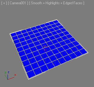
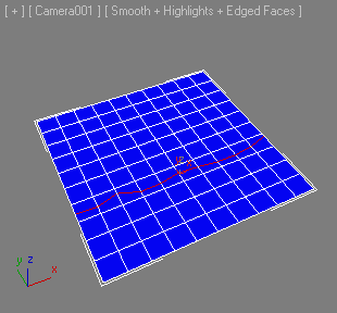
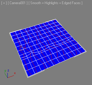
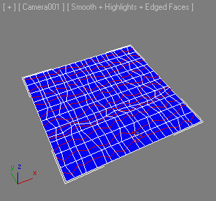
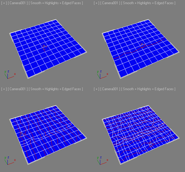
Connects edges and randomizes the position of the newly created vertex within each edge.
Returns true on success, false on failure (for example, if called while not in Edge Sub-Object Level).
The first argument controls the Random Jitter factor.
-
A jitter value of 0 produces a connection through the centers of the selected edges without any randomness.
-
A value of 0.5 jitters the position of the new vertices within the length of the edge (between its two vertices).
-
Values above 0.5 will produce vertices outside the selected edge, potentially causing polygon overlaps and z-fighting geometry.
The second argument controls whether the initial selection needs to be expanded to neighbor edge loops to facilitate connecting when the initial selection is not enough to produce any.
-
If set to false, connections will be produced only within the initial selection.
-
If set to true, the initial selection will be expanded first by selecting edge rings from the existing selected edge loops, then the resulting selection will be used to create the random connections.
Edges Panel
Spins the selected edge/edges in the polygon, changing their direction.
Returns true on success, false on failure.
Inserts the specified number of vertices in the selected edges. The inserted vertices are evenly spaced along the edge.
Returns true on success, false on failure.
Geometry (All) Panel
Remove triangulation from the model to achieve mainly four sided polygons.
When withinSel is set to true, applies to the current sub-object selection only.
When selectOnly is set to true, does not remove, but only selects the edges to be removed.
Loop Tools
Centers edges or edgeloops on the edgerings they are on and places the vertices in the middle of the edges.
Select an edge or more edges and apply.
If the autoLoop argument is true , the selection will be automatically looped.
Spaces the vertices evenly along the selected edges/edgeloops so that the distances between the vertices become equal.
If the autoLoop argument is true, the selection will be automatically looped.
If the SHIFT key is pressed while this method is being executed, it will also space loops on the top and bottom of a cylinder.
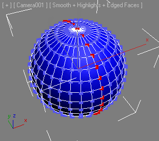
Adjusts each set of selected edges/edgeloops into smooth curves.
The curvature of each loop is determined by the position of the selected vertices along the loop. Think of the curve that you can create as a spline going from the endpoints of the edges/loop with a smoothly interpolated spline knot at each selected vertex.
If the autoLoop argument is true , the initial selection will be automatically looped before the tool is applied.
If the spaceLoop argument is true , all vertices will be evenly spaced along the loop.
If the spaceLoop argument is false , the initial relationship between vertices on the loop will be kept.
Straightens each set of selected edges/edgeloops into straight lines.
If any of the vertex "endpoints" of the set of edges/edgeloop are selected, the line will go from the first edge that the selected vertex is on and straight out from that edge. If no vertices are selected, the line will go between the two endpoints of the edges/edgeloop.
If the autoLoop argument is true , the initial selection will be automatically looped before the tool is applied.
If the spaceLoops argument is true , all vertices will be evenly spaced along the loop.
If the spaceLoops argument is false , the initial relationship between vertices on the loop will be kept.
If the SHIFT key is pressed while this method is being executed, it will also straighten loops on the top and bottom of a cylinder.
Turns each set of selected edges/edgeloops into the form of a circle.
The selected vertex along each loop determines the beginning point for the circle.
For open loops one of the "endpoints" of the edges/loop must be selected.
For closed loops (like around a cylinder), the vertex you want to least have change position must be selected.
If the autoLoop argument is true , the initial selection will be automatically looped before the tool is applied.
If the SHIFT key is pressed while this method is being executed, it will also circle loops on the top and bottom of a cylinder.
Tip: Make sure that the vertex next after the first on the loop goes in the general direction of the intended circle so that the circle is not "inverted".
Relaxes/smooths out the curvature of each set of selected edges/edgeloops.
Call multiple times to relax more.
If the autoLoop argument is true, checked the initial selection will be automatically looped before the tool is applied.
If the SHIFT key is pressed while this method is being executed, it will also relax loops on the top and bottom of a cylinder.
Symmetry
Collects symmetry data from the node specified as the first argument.
The second argument defines the symmetry axis as name- #x, #y, or #z.
The third argument defines the position variation threshold to use when searching for symmetry vertices.
Copies the vertex positions from the positive side of the symmetry axis to the negative side.
The axis argument can be either #x, #y, or #z.
Corresponds to the "+To-" button in the Symmetry Tools floating dialog.
Copies the vertex positions from the negative side of the symmetry axis to the positive side.
The axis argument can be either #x, #y, or #z.
Corresponds to the "-To+" button in the Symmetry Tools floating dialog.
Swaps the symmetry data about the specified axis.
Copies the vertex positions of the currently selected vertices into an internal "clipboard".
Pastes the vertex positions back onto the same vertices, even if not selected.
Other Modeling Methods
Hides either selected polygons or selected vertices based on the current sub-object level.
| Sub-Object Level |
Function |
| Polygon |
Select polygons and apply to hide them. |
| Edge |
Not supported. |
| Vertex |
Select vertices and apply to hide them. |
Rotates the current sub-selection at the specified degree in the coordinate system defined by the second argument counter-clockwise relative to the view direction specified by the third argument.
Returns true on success, false on failure. For example, if not in a sub-object level.
Mirror the selected element about the specified axis.
If the clone argument is passed as true, the element will be duplicated.
If the clone argument is false, the original element will be mirrored.
Returns true on success, false on failure.
Creates a Polygon from the vertex indices provided by the bitarray argument.
Returns the index of the new polygon.


