The following are the attributes for the DirectX 11 Shader node, with the AutodeskUberShader.fxo shader file assigned.
In order to use this shader, you must be working in the DirectX 11 environment in Viewport 2.0 and have the dx11Shader.mll plug-in enabled. For more information, see Using DirectX 11 with Viewport 2.0.
You can find the DirectX 11 Shader in the Hypershade Create tab. The AutodeskUberShader.fxo file is automatically loaded when the shader is created.
The dx11Shader.mll plug-in lets you load and view HLSL shaders in Viewport 2.0. When you create a DirectX 11 shader using the Hypershade, the AutodeskUberShader.fxo file is automatically connected; however, you can also load your custom HLSL shader. Alternatively, other sample HLSL shaders are available at <maya directory>\presets\HLSL11\examples\.
The dx11Shader_defaults preset is provided. You can use this preset to revert the parameters back to the values initially compiled with the shader.
For information regarding mip map levels, see mipmaplevels on this page: Semantics and annotations supported by the dx11Shader and glslShader plug-ins in Viewport 2.0.
- Shader
- Light Binding
- Lighting
- Ambient and Emissive
- Diffuse
- Opacity
- Specular
- Normal
- Reflection
- Tessellation and Displacement
- Translucency
- UV
- Surface Data
- Default Texture Data
- Supported image formats
Shader
- Shader File
- Navigate to your shader file to assign it to your
DirectX11 Shader.
The DirectX 11 Shader searches for the .fx files in the following locations and in the following order:
- `workspace -q -rd`
- `workspace -q -rd` + "/renderData/shaders"
- `workspace -fre shaders`
- `getenv("DX11SHADER_ROOT")`
- `getenv("DX11SHADER_ROOT")` + "/shaders"
- ${MAYA_LOCATION}/presets/HLSL11/examples
The ` denotes executing either a MEL or C function to obtain the required value.
Note: The AutodeskUberShader.fxo file, as well as other sample HLSL11 shaders, are provided in <maya directory>\presets\HLSL11\examples\.Click
 to reload your
.fx file and
to reload your
.fx file and
 to edit it in your default text editor.
- Technique
- These options provide different shading methods within the same shading material.
Note: The following lists the different techniques for the AutodeskUberShader. Different shaders have different techniques to achieve a variety of effects.Tip: You can change the technique for multiple dx11Shaders in one step by using the Channel Box, or by setting the Technique value in the Attribute Spread Sheet. Use integers to set the Technique values in the Attribute Spread Sheet. TessellationOFF = 0, TessellationON = 1, and WireFrame =2. This shortcut is only applicable to changing multiple instances of the same fx shader.
-
TessellationOFF: This is the default option and simply displays the mesh in the workspace without any tessellation.
-
TessellationON: This option uses shading level tessellation to provide a smoother model without the need for extra geometry.
-
WireFrame: This option provides a wireframe version of the tessellated mesh so that you can review the tessellation of the TessellationON feature.
-
Light Binding
- Light0 / Light 1 / Light 2
-
If you select the Automatic Bind option, Maya automatically assigns the lights in the scene to the shader. If there are less than three lights in your scene, then light 1 and/or light 2 are left unbound until a new light is created. If this option is selected, Maya indicates the light that is bound for each of Light0 / Light 1 / Light 2.
Use the navigation icon
 to access the connected light shape
Attribute Editor.
to access the connected light shape
Attribute Editor.
You can also select Use Shader Settings to refrain from binding a light. This way, you can tweak the light properties via the Light 0 / Light 1 / Light 2 attributes in the DirectX 11 Shader Attribute Editor.
You can also manually bind your lights. Select, from the drop-down list, the lights from the scene that you want to bind the shader to.
The AutodeskUberShader supports point lights, spot lights, ambient lights, or directional lights.
Caution: After binding a light, you cannot change its parameters in the dx11Shader Attribute Editor. Instead, you must make changes from the light Attribute Editor.Note: When the DirectX 11 Shader is loaded, Maya automatically binds the lights that are set to Automatic Bind. All parameters sharing the same Object attribute are considered to define one light. If a specific light keyword, that is, ambient/point/spot/directional, is found in the Object attribute string, then Maya connects the first light of this type found in the scene. Once this is done, any unconnected lights are connected to remaining scene lights based on position/direction parameter compatibility.Tip:If you select Automatic Bind under Light Binding, and you have more than one ambient light in your scene, then all ambient lights in your scene are merged as one for viewport rendering, and only one of Light 0/Light 1/Light 2 indicates Ambient as a result.
If you manually bind the ambient lights, then each of the manually bound individual lights are specified under Light 0/Light 1/Light 2.
Parameters
Lighting
- Linear Space Lighting
- Disable this option to refrain from correcting gamma in the textures. Enabling this option assumes that the textures have gamma applied and therefore removes this gamma and re-applies it later on.
- Shadows
- Select this option to enable shadow casting.
- Shadow Strength
- Use this slider to control the intensity of the shadows.
- Shadow Bias
-
Sometimes, real-time shadows can cause artifacts on your objects caused by limited precision in the shadow map or differences in scene scale. Use this attribute to remove shadow artifacts on your object.
- Double Sided Lighting
- Select this option to reverse the backfacing normals of a double-sided, transparent object to improve its lighting.
Note: When this option is enabled, backfacing polygons caused by negative scaling may turn black. You should reverse vertex normals after scaling negatively.
- Rim Light Min / Rim Light Max / Rim Light Brightness
- Use these options to simulate a rim light in your scene to highlight edges of objects. Use Rim Light Min and Rim Light Max to set the falloff from bright to dark. Rim Light Max is the distance from the edge at which falloff begins. Rim Light Min is the distance from the edge at which the falloff ends.
Light 0
- Enable Light 0
- Select this option to enable the specified light in the shader.
Note: The following parameters are repeated for Light 0, Light 1 and Light 2.
- Light 0 Type
- Select the type of light, for example, spot, point, directional or ambient. The Default and None options are used internally by the dx11Shader.mll plug-in. Selecting either of these options results in a point light.
- Light 0 Position
- Use this attribute to set the position of the light.
Note: If the light is not bound to a Maya light, you can right-click to manually connect existing lights, cameras, locators and so forth to this attribute.Note: Press 7 for scene lighting.
- Light 0 Color
- Customize the color for your light. Click the swatch either to change the light’s color in the Color Chooser or to map a texture to the light.
- Light 0 Intensity
- Use this attribute to set the brightness of the light. A light with an intensity value of 0 produces no light. A light with a negative intensity value removes light from a scene in the area of the light’s influence.
- Light 0 Direction
- Use this attribute to set the direction of your light.
- Light 0 Cone Angle
- Use this attribute to set the cone angle for your spotlight. This is the angle (in degrees) from edge to edge of the spot light’s beam.
- Light 0 Penumbra Angle
- Use this attribute to set the penumbra angle for your spotlight. This is the angle (in degrees) from the edge of the spot light’s beam over which the intensity of the spot light falls off linearly to zero.
- Light 0 Decay
- Use this attribute to control how quickly the light's intensity decreases with distance. For more information, see Decay Rate in Area Light options.
Ambient and Emissive
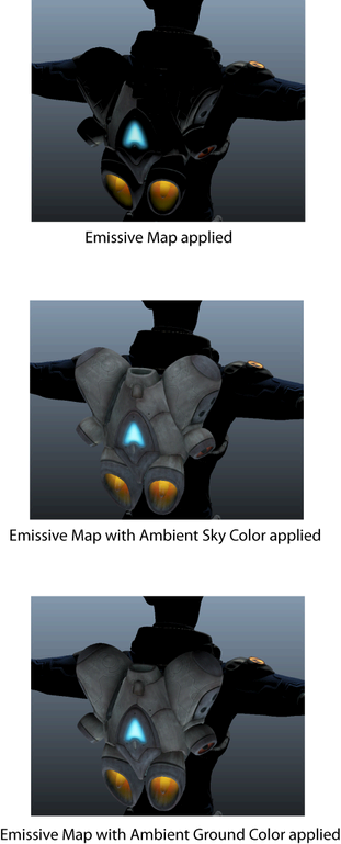
- Emissive Map
- Enable this option and connect a file texture to Emissive Map to apply an emissive texture that is bright like a light source. To stop using the texture, disable Emissive Map.
- Emissive Intensity
- Use this attribute to control the amount that the emissive map contributes to the shader.
- Ambient Sky Color / Ambient Ground Color
- Use these options to brighten the object by simulating light coming from the ground or sky.
- Ambient Occlusion Map
- Select this option to add ambient occlusion to your scene. Connect a pre-baked map that affects only ambient light in the shader.
Diffuse
- Diffuse Model
- Select among three diffuse shading methods, depending on your object. Select Blended Normal (Skin) so that the diffuse lighting on an object is more realistic for simulating skin. Select Soften Diffuse (Hair) to simulate the diffuse lighting for hair. Select Lambert for other models.
- Diffuse Map / Diffuse Map Alpha
- Select
Diffuse Map to apply a diffuse texture to your object to tint it. Connect your texture to the
Diffuse Map attribute. Select
Diffuse Map Alpha to apply the texture's alpha information to the opacity of the object.
Note: Use of the Depth Peeling Transparency Algorithm with Diffuse Map Alpha is currently not supported.
- Diffuse Color
- You can also tint your object using Diffuse Color.
- Lightmap Map
- Select Lightmap Map to apply a baked shadowmap. The shadowmap is then multiplied with the diffuse to create baked shadows.
- Blended Normal Mask
- Use this option to apply different amounts of blended normal diffuse to different parts of the object.
- Blended Normal
- This option is a blended normal diffuse. Increase this value to create the light bouncing effect, softening the appearance of the skin.
- IBL Map
-
Use this feature to add image based lighting to your scene. You can connect a .dds cube map or a 2D spherical or latlong map; or, a combination of a cube map and a 2D map.
This feature allows you to rapidly prototype your character in different lighting environments.
- IBL Cube Map
- Select this option to connect a .dds cube map.
- IBL 2D Map
- Select this option to connect a 2D spherical or latlong map.
- IBL Type
- Select from the drop-down list the type of IBL map(s) that you are connecting. You can connect a .dds cube map or a 2D spherical or latlong map; or, a combination of a cube map and a 2D map.
- IBL Intensity
- Use this slider to increase or decrease the intensity of your image based lighting.
- IBL Blur
- Use this slider to blur the image based map.
- IBL Rotation
- Use this slider to rotate your IBL map; for example, if you want the sun in your IBL map to appear elsewhere on your object.
- IBL Spherical Pinch
- Adjust this attribute to reduce pinching artifacts that may occur with some spherical maps.
Opacity
- Opacity
- Use this attribute to control the transparency of the object.
- Opacity Mask
- Use this attribute to apply a texture that specifies the areas of the object that are fully transparent.
- Opacity Mask Bias
- Use this attribute to set the threshold below which the pixels in the opacity mask become fully transparent. For example, if set at 0.5, all pixels in the opacity mask with a value smaller than 0.5 become completely invisible.
- Opacity Fresnel Min / Opacity Fresnel Max
- Use these attributes to adjust the opacity of the object based on the viewing angle. Use Opacity Fresnel Min to adjust the opacity for faces that are parallel to the camera and Opacity Fresnel Max to adjust the opacity for faces that are perpendicular to the camera.
Specular
- Specular Model
- Select among three specular shading methods, depending on your model. Select Kelemen-Szirmaykalos (Skin) to perform Kelemen-Szirmaykalos specular calculations to better simulate human skin. Select Anisotropic (Brushed Metal/Hair) to add anisoptropic specular lighting to simulate metal or hair. Select Blinn shading for other models.
- Specular Map
- Select Specular Map to increase or decrease the amount of specularity on the object based on the values in the texture. The RGB channels in the specular map controls the Specular Color, while the alpha channel in the specular map controls the Specular Power.
- Specular Color
- Specular Color controls the brightness and color of the specularity.
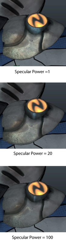
- Specular Power
- Specular Power controls the shape of the specular highlight.
- Anisotropic Direction Map
- If you select the
Anisotropic (Brushed Metal/Hair) option under
Specular Model, you can optionally add a directional map to control the direction of the anisotropic highlight. If you do not select this option, you can still use the
Anisotropic Specular Color and
Anisotropic Roughness options to control the color and shape of your specular highlight.
Note: Currently, you must use a tangent space map.
- Anisotropic Direction Type
- Select from the drop-down list the type of direction map you are connecting to the Anisotropic Direction Map attribute.
- Anisotropic Specular Color
- Use this option to control the color of your specular highlight.
- Anisotropic Roughness
- Use this option to control the shape of your specular highlight.
- Mix Blinn-Anisotropic by Direction Alpha
- Select this option to blend between Blinn and anisotropic specular lighting based on the alpha channel in the direction map.
Normal
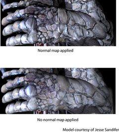
- Normal Map
- Select
Normal Map to simulate the lighting of bumps and indentations from the details baked into the normal map.
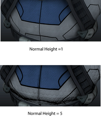
- Normal Height
- Use the
Normal Height option to change the height of the bumps in the normal map texture.
- Support Non-Uniform Scale
- Select this option to correctly display normals for objects that have non-uniform scaling applied.
- Normal X (Red) / Normal Y (Green)
- Use these options to set whether the red and green channels of your normal map are positive or negative.
Important: For this option to work correctly, you must ensure that Tangent Space > Coordinate System is set to Right Handed under the shape node.
Reflection
- Reflection Map
- Select this option to use a reflection map in your scene.
- Reflection Type
- You can connect a .dds cube map or a 2D spherical or latlong map; or, a combination of a cube map and a 2D map. Select from the drop-down list the type of map(s) you are using.
- Reflection Cube Map
-
Select the Reflection Cube Map option to include reflection in your scene. A Reflection Cube Map allows you to create more realistic pre-baked reflections. Use this option to connect a .dds cube map.
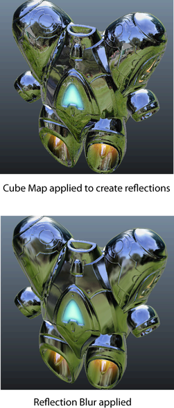 Tip: You can generate cube maps using freely available third party tools.
 - Reflection 2D Map
- Select this option to connect a 2D spherical or latlong map.
Tip: IBL and reflection maps should be in the same color space as your other input textures. When using the Linear Space Lighting setting in the AutodeskUberShader, input textures are expected to be in sRGB display space; therefore, IBL and reflection maps that are not in sRGB color space should be converted into this space through image editing software.
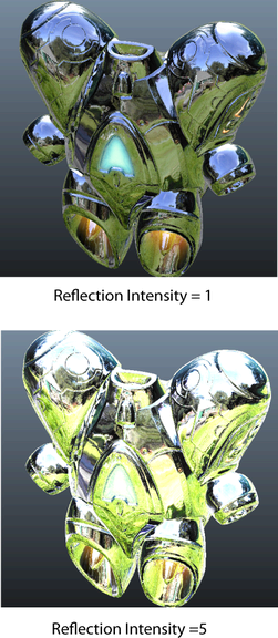
- Reflection Intensity
- Use this slider to adjust the intensity of the reflection on your object.
- Reflection Blur
- Use this option to create a blurred reflection effect. This option gives you more control over the type of metal or material you are trying to simulate.
- Reflection Rotation
- Use this option to rotate your reflection map.
- Reflection Spherical Pinch
- When using spherical reflection maps, you can use this option to reduce the pinching artifacts that some spherical maps may exhibit.
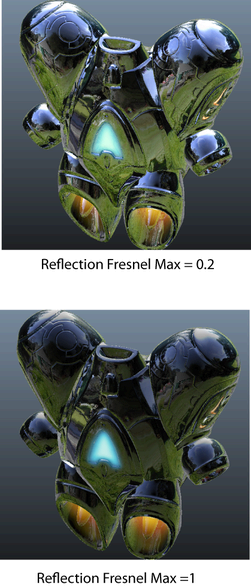
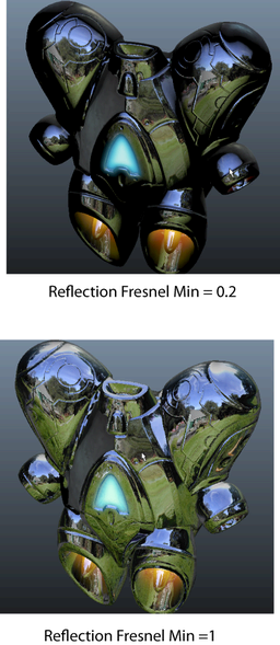
- Reflection Fresnel Min / Reflection Fresnel Max
-
Use Reflection Fresnel Min and Reflection Fresnel Max to adjust the amount of reflection based on whether a face is parallel to or perpendicular to the camera.
Use Reflection Fresnel Min to add more reflection to the faces of the object that are facing the camera.
Use Reflection Fresnel Max to add more reflection to the faces of the object that are perpendicular to the camera.
These options work best for curved objects.
- Reflection Mask
- Use these options to apply a texture to mask areas to prevent them from receiving reflection.
- Spec Alpha for Reflection Blur
-
Enable this option to use the alpha channel of the specular texture to determine the amount of reflection needed to blur parts of the object. Disable this option to evenly blur the reflection everywhere on the object.
- Spec Color to Tint Reflection
- Enable this option to use the specular color to tint the color of the reflection. The reflection map is not tinted if this option is disabled.
- Reflections Affect Opacity
- Select this option so that areas on the object that have reflection or specularity do not become fully transparent (for example, like a soap bubble). When disabled, reflections and specular lighting do not affect opacity (for example, with semi-transparent objects such as hair).
Tessellation and Displacement
- Displacement Model
- Select from the drop-down list whether you are using a greyscale displacement map or a tangent vector map. You can create vector displacement maps in Mudbox. However, you must use the same low polygon model in Maya as you do in Mudbox.
When using a vector displacement map, you usually also want to provide a normal map to the shader to provide the correct normals to the shader after the vector displacement map has moved the vertices.
Note:If you are using .exr files for greyscale displacement maps, you do not need to adjust the Displacement Offset or Displacement Height values and the default settings should work automatically. If you are using .exr files for tangent vector displacement maps, you should set your Displacement Offset to 0 and your Displacement Height to 1.
This does not apply to .tif files, in which case you must adjust the Displacement Offset or Displacement Height values manually.
Note: Select Tangent as your Coordinate Space if you output your normal map from Mudbox. Select Absolute Tangent as your Vector Space if you output your vector displacement map from Mudbox. - Displacement Map
-
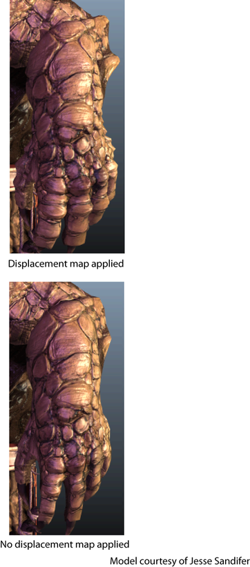
Select Displacement Map to use displacement maps. Displacement maps extrude or indent vertices of your mesh. Displacement maps are especially useful when used in combination with tessellation to generate additional details in your object.
The benefit of displacement maps over normal maps is that shadows pickup the new details of the displacement map.
- Displacement Coordsys
- Select the correct displacement axis for vector displacement maps. The axis is determined by the application from which you generated the vector displacement map, for example, Mudbox.
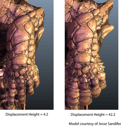
- Displacement Height
- Use this attribute to scale your displacement.
- Displacement Offset
-
Use this attribute to control the base value for your displacement.
For example, if the offset is set to 0.5, a gray color is not displaced. An offset of 0 would produce an indentation. An offset of 1 would extrude.
Likewise, if the offset is set to 0, a black color is not displaced. An offset of 0.5 would extrude half as much as an offset of 1.0. Indentations do not occur.
- Displacement Clipping Bias
- In cases of extreme displacement, Maya may clip away faces inadvertently. This may occur in scenes with a landscape or objects that are long and wide. Use this attribute to set the maximum displacement to determine when a face of an object is clipped from view. You can also use Bounding Box Extra Scale to avoid inadvertently clipping your object.
- Bounding Box Extra Scale
- Use this option to control the bounding box to avoid inadvertently clipping your object when displacement is used.
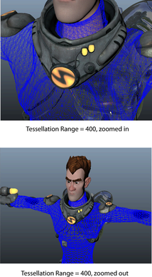
- Tessellation Range
- When you set this attribute, tessellation is controlled by the distance of the object from the camera.
Note: You may find it easiest to enable WireFrameON when adjusting the tessellation settings.
- Tessellation Minimum
-
Value of tessellation that is constant throughout the mesh. A value of 1 means no tessellation.
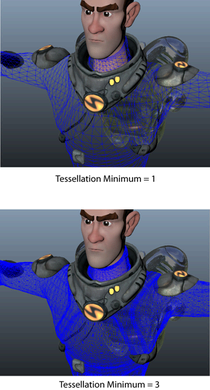
Increase the Tessellation Minimum value to increase the resolution.
- Flat Tessellation
- Select this option to blend point normal tessellation (which smooths the edges of the object) with Flat Tessellation (which only tessellates but does not smooth the object). Set this value to 1 to disable the smoothing.
Translucency
- Translucency
- The
Translucency feature simulates light passing through an object. For example, if simulating human skin, the skin becomes more red. Select this attribute to use the options below.
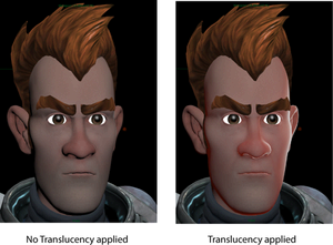 Note: Use these options to add translucency to your object. This option simulates light passing through the object to give it a more realistic look.
 - Thickness Mask
-
The Thickness Mask is a texture you render to control the amount of light that passes through certain areas of the skin. For example, non-bony areas with thin skin like the nose would have a reddish color, since a lot of translucency is coming through. By contrast, bony areas would have a darker color in the thickness texture.
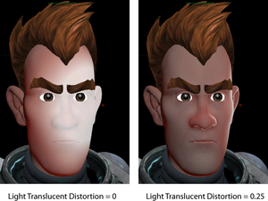
- Light Translucent Distortion
-
Use this value to set the amount that the normal (per pixel) influences the translucency.
If set to 0, the translucency is uniform over the entire object.
If set to greater than 0, for example 0.5; the translucent effect is no longer uniform but is instead broken up and distorted based on the normal. The result appears more organic.
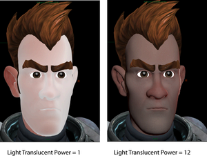
- Light Translucent Power
- Use this attribute to change the focus or size of the translucent areas.
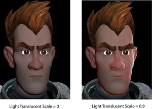
- Light Translucent Scale
- Use this option to adjust the amount of translucency created by the light behind the object. When you adjust the slider to 0, there is no translucency in your object.
- Translucent Minimum
- This attribute sets the amount of translucency that an object always has, even if there is no light behind it.
- Outer Translucent Color / Medium Translucent Color / Inner Translucent Color
- Use these options to change the skin translucency color; for example, for a creature with different colored skin.
UV
You can bind a UV set to each of your texture maps. To do so, you must first bind the UV set to the DirectX 11 Shader. You can bind up to 3 UV sets under the Surface Data section. Map your UV set to each of TexCoord 0/1/2 where applicable. You can then use this drop-down list to select the texture co-ordinates (in other words, UV set) that you want to map each texture map to. See Assigning a UV set to a texture map connected to the DX11 AutodeskUberShader for more information.
Surface Data
This section specifies the channels of the geometry, such as normals and tangents, that are passed into the shader.
 for the available options.
By default, TexCoord0 is mapped to UV set map1 and TexCoord1 is mapped to map2 and so forth. If you use UV sets with different names, you can bind them to the shader by specifying them in the TexCoord0/1/2 fields. Use uv: in front of your UV set name. For more information, see Assigning a UV set to a texture map connected to the DX11 AutodeskUberShader.
Default Texture Data
Use these options to select the default texture displayed in the UV Texture Editor when a UV set is selected. For example, if UV map1 is mapped to TexCoord0, and TexCoord0 is mapped to Diffuse Map, then when you select UV map1 in the UV Texture Editor, the Diffuse Map texture is displayed.