Use these options to set the attributes of primitives such as spheres or cubes that you create from the menu. See also Create polygon primitives.
Sphere
- Radius
-
Specifies the distance from the center of the sphere in all directions. (For interactive creation, appears as a single-click setting only.)
Cube
- Width
-
Specifies the width of the cube.
- Height
-
Specifies the height of the cube.
- Depth
-
Specifies the depth of the cube.
Cylinder
- Radius
-
Specifies the distance from the center of the cylinder. (For interactive creation, appears as a single-click setting only.)
- Height
-
Specifies the height of the cylinder. (For interactive creation, appears as a single-click setting only.)
Cone
- Radius
-
Specifies the distance from the base of the cone in all directions. (For interactive creation, appears as a single-click setting only.)
- Height
-
Specifies the height of the cone. (For interactive creation, appears as a single-click setting only.)
Plane
- Width
-
Specifies the distance along the x axis (by default). (For interactive creation, appears as a single-click setting only.)
- Height
-
Specifies the measurement along the y axis (by default). (For interactive creation, appears as a single-click setting only.)
Torus
- Radius
-
Specifies the distance from the center of the torus in all directions. (For interactive creation, appears as a single-click setting only.)
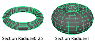
- Section Radius
-
Specifies the size of the sections that make up a torus. Change this value to increase or decrease the radius of these sections.
- Twist
-
The Twist option value specifies the twist angle of the torus. Change this value to adjust the distance around the torus in all directions.
Prism
A prism is a polyhedron with two polygonal faces lying in parallel planes and with the other faces parallelograms.
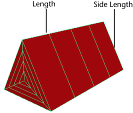
When creating a prism, you can set the following options:
- Length
-
Enter values or use the slider to specify the length of the prism (the distance between the two polygonal faces). (For interactive creation, appears as a single-click setting only.)
- Side Length
-
Enter values or use the slider to specify the side length of the prism’s polygonal caps. (For interactive creation, appears as a single-click setting only.)
- Number of Sides
-
Enter the number of sides for the ends of the prism. The above example is a triangular prism (3 sides). The size and volume of the prism increases with the number of sides if the edge length and length/height are kept constant.
Pyramid
A pyramid is a polyhedron with a polygon base and triangles with a common vertex for faces. Maya creates 3-, 4-, or 5-sided pyramids with equilateral triangles.
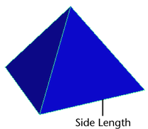
When creating a pyramid, you can set the following options:
- Side Length
-
Enter values or use the slider to specify the side length of all faces. (For interactive creation, appears as a single-click setting only.)
- Number of Sides in Base
-
Select the number of sides for the base of the pyramid (3, 4, or 5).
Pipe
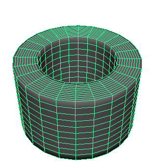
The options are very similar to the options for the cylinder polygonal shape, with the addition of Thickness (which specifies the thickness of the wall).
- Radius
-
Specifies the distance from the center of the pipe in all directions. (For interactive creation, appears as a single-click setting only.)
- Height
-
Specifies the height of the pipe. (For interactive creation, appears as a single-click setting only.)
- Thickness
-
Specifies the thickness of the pipe walls.
Helix
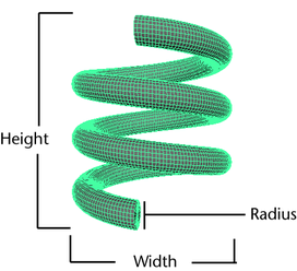
A helix is a curve in three dimensional space that lies on a cylinder, so that its angle to a plane perpendicular to the axis is constant.
- Coils
-
Specifies the number of coils.
- Height
-
Specifies the height of the helix. (For interactive creation, appears as a single-click setting only.)
- Width
-
Specifies the width of the helix. (For interactive creation, appears as a single-click setting only.)
- Radius
-
Specifies the radius of the helix coils. (For interactive creation, appears as a single-click setting only.)
- Direction
-
Specifies the direction of the helix’s twist: clockwise or counterclockwise.
Soccer Ball
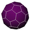
The soccer ball is a truncated icosahedron: thirty-two faces, alternating hexagons and pentagons.
For this shape, you can set the following options:
- Radius
-
Enter values or use the slider to specify the radius of the soccer ball. (For interactive creation, appears as a single-click setting only.)
- Side Length
-
Enter values or use the slider to specify the side length of the soccer ball. (For interactive creation, appears as a single-click setting only.)
Platonic Solids
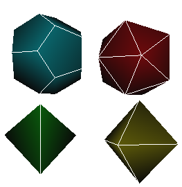
You can create many different types of polygonal platonic solids. Platonic solids are shapes where all sides are equal, all angles are the same, and all faces are identical. These are:
- Tetrahedron: four triangular faces
- Octahedron: eight triangular faces
- Dodecahedron: twelve pentagonal faces
- Icosahedron: twenty triangular faces
(The cube—the fifth platonic solid—has a separate listing in the primitives.)
You can switch between these types by selecting Solid Type in the Attribute Editor or in the option box for Platonic Solids.
For these four shapes, you can set the following options:
- Radius
-
Enter values or use the slider to specify the radius of the platonic solid. (For interactive creation, appears as a single-click setting only.)
- Side Length
-
Enter values or use the slider to specify the side length of the platonic solid. (For interactive creation, appears as a single-click setting only.)
- Platonic type
-
You can switch between platonic solid types in the options for these shapes.
Interactive Creation
You can position and scale primitives as you create them using your mouse, without having to use transformation tools. This option stays on until you turn it off. For more information, see Create polygon primitives.
Exit on Completion
This option interacts with Interactive Creation. When Exit on Completion is turned on, you must select a primitive type again in order to create another primitive. When this option is turned off, you can interactively create multiple primitives of the same type, until you select another tool.
Common settings for polygon primitives
Divisions
The values you enter in these boxes change the primitive by adding or taking away faces of the polygonal surfaces.
Almost all primitives allow you to subdivide along the height axis. The exception is the helix, which subdivides per coil instead.
Primitives with radial symmetry allow you to subdivide around the axis. These include spheres, cylinders, cones, tori, pipes, and helixes.
Primitives with caps allow you to subdivide the caps. These include cylinder, cones, pipes and helixes.
The plane allows subdivisions along the width axis, and the cube allows subdivisions along both the width and depth.
- Axis divisions
-
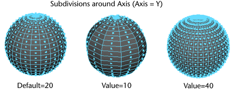
This option defines the number of subdivisions there are around the axis. This option is called Subdivisions Axis in the Channel Box and the Attribute Editor.
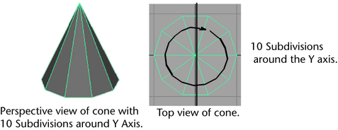
Increase or decrease this value to add or take away faces around the axis defined by the Axis option.
- Height divisions
-
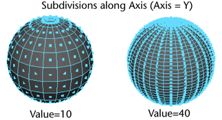
This option defines the number of subdivisions there are along the axis defined by the Axis option. Height is equivalent to the Y direction by default. This option is called Subdivisions Height in the Channel Box and the Attribute Editor. Increase or decrease this value to add or take away faces in the Axis direction.
- Depth / Width, Depth divisions
-
When Axis is set to X or Y, depth is equivalent to the Z direction for polygonal cubes. When Axis is set to Z, depth is equivalent to the Y direction. This option is called Subdivisions Depth in the Channel Box and the Attribute Editor. Increase or decrease this value to add or take away faces along the depth.
- Cap divisions
-
Caps are the tops, bottoms, or sides of cones, cylinders, prisms, pyramids, pipes, and helixes. This option defines the number of subdivisions around the origin of the primitive caps. This option is called Subdivisions Cap in the Channel Box and the Attribute Editor. Increase or decrease this value to add or take away faces around the caps.

- Round Cap
-
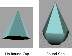
This option allows you to create a round surface for the cap. Your Subdivisions Cap value must be one or greater to see the round cap effect. This option applies to the Cylinder, Cone, Pipe, and Helix primitives.
Axis
This option does not appear in Interactive Creation.
To set the axis for your primitive during interactive creation, you can use the orthogonal views. Whichever view you create your primitive in—top, front, or side—is the way your primitive’s axis will be aligned (y, z, or x).
By default, a primitive is created along the Y axis. You can change a primitive’s default orientation before you create it by changing the Axis option.
You cannot change the orientation for a new primitive from the Channel Box, but you can enter values in the Axis boxes in the Attribute Editor.
Create UVs
The following table lists the common Create UVs attributes for each type of polygon primitive.
| Shape | Normalize | Preserve Aspect Ratio | Other Options |
|---|---|---|---|
|
Sphere |
Yes |
||
|
Cube |
Yes |
Yes |
|
|
Cylinder |
Yes |
Yes |
|
|
Cone |
Yes |
Yes |
|
|
Plane |
Yes |
||
|
Torus |
|||
|
Prism |
Yes |
Yes |
|
|
Pyramid |
Yes |
Yes |
|
|
Pipe |
|||
|
Helix |
Yes |
Yes |
|
|
Soccer Ball |
Yes |
Yes |
|
|
Platonic Solids |
Yes |
Yes |
For details on Create UVs attributes, see:
Preparing a primitive for texture mapping
UV texture coordinates are assigned for texture mapping by default. If you do not plan to map textures on a polygonal primitive, you can turn off the Create UVs option in the options window.
Important note about UVs
If UVs are not present on an object, you cannot see mapped textures. This can happen if you inadvertently create a primitive object with the Create UVs option turned off.
To correct the problem, select the faces of the primitive and use any of the mapping items in the Edit UVs menu.
You can then use the UV Editor to view the created UVs. Select the object and use any of the UV creation or editing Create UVs menu items.
Texture mapping options for primitives with faces or caps
The options window for primitives with faces or caps includes a Create UVs menu where you can select how you want the texture map to cover the primitive when you assign it. This Create UVs menu is also available from the Attribute Editor.
Create UVs
(Default.) This option assigns UV texture coordinates on the primitive for texture mapping.
The various normalization settings fit the UVs within the 0 to 1 texture space. Normalize Collectively and Preserve Aspect Ratio is the default setting.
- Normalization Off
-
No normalization occurs and the texture remains its true size.
- Normalize Collectively
-
This option maps the texture over each face of the primitive and normalizes it so that it covers the entire object.
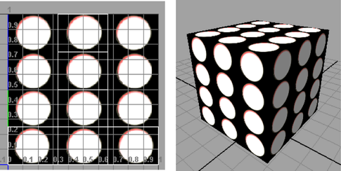
- Normalize Each face Separately
-
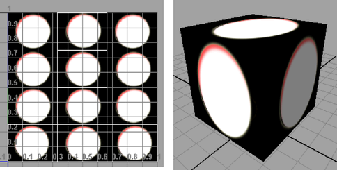
Only available for Cubes, Soccer Balls and Platonic Solids.
If you select this option, Maya maps the texture to each face separately.
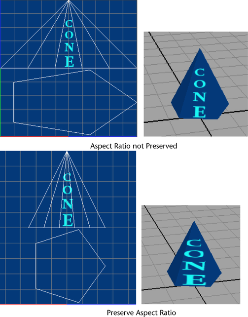
- Normalize Collectively and Preserve Aspect Ratio
-
(Default.) Normalized UVs maintain the original ratios of the UVs without stretching the UVs to fill the 0 to 1 texture space. This option affects the appearance of the texture map on the primitive.
UV options for primitive spheres
The options window for a polygonal sphere primitive includes a Create UVs menu where you can select an item to specify how you want the texture map to behave at the poles. This Create UVs menu is also available from the Attribute Editor.
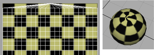
- Pinched at poles
-
Creates a UV texture map where the rings of triangles around the poles are treated as triangles with a single common vertex (the pole).
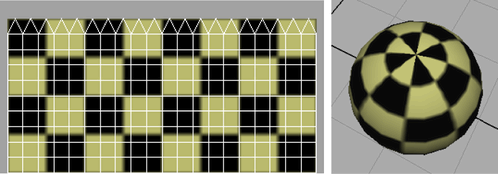
- Sawtooth at poles
-
(Default.) Creates a UV texture map where the rings of triangles around the poles are treated as individual triangles, giving the edges of the UV map a sawtooth look. Often, this looks better in the 3D view; however, it also introduces texture borders, which may not always be desirable.
Adjust primitive after creation
When Interactive Creation is turned on for primitives, you can optionally modify the subdivisions for a primitive using the following options. These options exist only for primitives that possess subdivision attributes.
- Adjust subdivisions after create
-
Adds additional steps to the Interactive Creation process that let you adjust the subdivisions for the primitive when interactively creating primitives. The number of additional steps is dependent on the primitive type. The default setting is on when Interactive Creation is turned on.
- Adjust cap subdivisions after create
-
Adds additional steps to the Interactive Creation process that let you adjust the cap subdivisions on primitives that contain caps (Cylinder, cone, pyramid, prism, helix, pipe). The default setting is off. This option can only be used when the Adjust subdivisions after create option is turned on.