All required input files listed in this example can be retrieved by executing the following command:
$ pan -t 02
After the above command is executed, a directory named 02 is created containing all files.
Problem description
A generic geometry of Inconel625 is built in a powder bed system and simulated. The layer height is 0.04 mm. The part geometry is imported in the analysis through an STL file, and it is automatically meshed within Local Simulation. The substrate is assumed to be 24 mm thick. The actual build plate is planned to have 5 similar geometries on it. Here, a simplified analysis is performed on just 1 of the geometries. The *PBDL card is used to add the deposition multiplier for the geometries that are not included in the analysis. The *PBIS card insulates the side of the small substrate in the analysis, simulating the effect of having other builds on the build plate nearby.
The *PBSS card constrains the sides of the small substrate in the analysis, mimicking the effect of being attached to the larger build plate. The build plate has an initial temperature of 100o C, which is modeled using *INIT. The resulting mesh is illustrated in Figure 2.1.
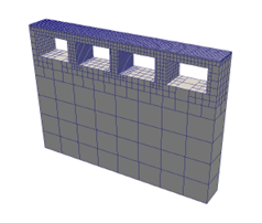
Figure 2.1: Coarse (.5mm) mesh
A time incremental thermal analysis is performed first to compute the temperature history of the part. Layers are activated in groups, and additional time increments are used to model heat conduction into the part. The thermal analysis includes only the part and substrate. Heat loss into the powder is modeled as convection with a value of 25.d-6 W/((mm2) – deg C) using the *CONV option.
A time incremental mechanical analysis is performed after the thermal analysis is completed. Similarly to the thermal analysis, layers are activated in groups using *PBPA and the computed temperature distribution from the mechanical analysis is used to compute deformation due to the thermal expansion. The input process parameter file (pp.prm) was generated in Example 1.