First look at the m1 warning.txt and m1 recoater.txt files to investigate possible build failure. The end of the warning file should look as follows:
*** WARNING: 15
Support structure failure
-------------------------------
-------------------------------
*** WARNING: 16
Support structure failure
-------------------------------
-------------------------------
*** WARNING: 17
Support structure failure
-------------------------------
This indicates some support structure failure will occur. Further investigation of the results will be required to determine the severity of this failure.
time (s), layer group, recoater clearance (%), top z deformed coord (mm), recoater coord (mm)
3.956736E+03 1 85.644 1.116574E+01 1.120000E+01
7.913572E+03 2 90.582 1.188377E+01 1.192000E+01
1.187041E+04 3 89.822 1.260407E+01 1.264000E+01
1.582724E+04 4 88.806 1.332448E+01 1.336000E+01
1.978408E+04 5 87.524 1.404499E+01 1.408000E+01
2.374092E+04 6 86.412 1.476544E+01 1.480000E+01
2.766260E+04 7 88.417 1.548463E+01 1.552000E+01
3.160185E+04 8 81.747 1.620730E+01 1.624000E+01
3.554814E+04 9 80.068 1.692797E+01 1.696000E+01
3.950498E+04 10 78.914 1.764843E+01 1.768000E+01
4.346181E+04 11 79.769 1.836809E+01 1.840000E+01
4.741865E+04 12 81.335 1.908747E+01 1.912000E+01
5.136494E+04 13 82.981 1.980681E+01 1.984000E+01
5.530420E+04 14 83.504 2.052660E+01 2.056000E+01
5.922588E+04 15 83.504 2.124660E+01 2.128000E+01
6.313701E+04 16 78.303 2.196868E+01 2.200000E+01
6.702177E+04 17 81.079 2.268757E+01 2.272000E+01
7.088896E+04 18 87.437 2.340503E+01 2.344000E+01
7.472627E+04 19 90.987 2.412361E+01 2.416000E+01
7.853193E+04 20 92.306 2.484308E+01 2.488000E+01
8.230420E+04 21 93.512 2.556260E+01 2.560000E+01
8.603779E+04 22 94.521 2.628219E+01 2.632000E+01
8.972920E+04 23 95.379 2.700185E+01 2.704000E+01
9.337490E+04 24 96.516 2.772139E+01 2.776000E+01
This indicates that recoater interference should not be an issue for this geometry. Now look at the simulation results.
Figure 11.2 shows the results for the 3rd to the last increment, before any elements have been removed, after clipping the part to show the center of the build. These values correspond as follows:
0 - Substrate or build plate
1 - Component
2 - Support structure
3 - Failed support structure
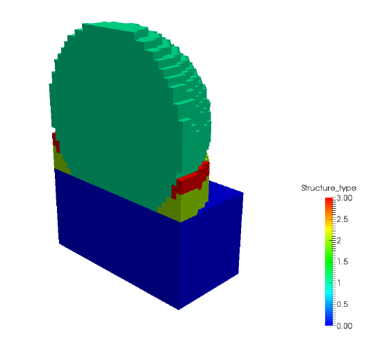
Figure 11.2 Structure type results
Observe that there are numerous failed supports, as indicated in both the simulation log file and the m1 warning.txt file. Let us examine the results to ensure these failures did not result in excessive distortion.
Figures 11.3 show the computed final distortion from the mechanical analysis (m1.in) after the part is removed from the build plate, and after the support material has been removed.
Observing these results show that despite the support structure failure, the part has maintained a high degree of dimensional accuracy. It is good engineering practice however to check these final dimensions to the tolerances of the part with respect to its end use.
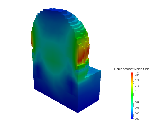
Figure 11.3 (a) After build plate bolt release
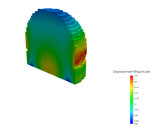
(b) After support and component release from build plate
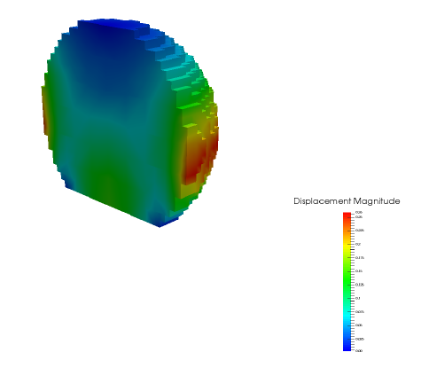
(c) After support material removal from the component