- Navigate to the example 09 folder using Windows (C:\Program Files\Autodesk\Netfabb Local Simulation 2017\examples\09).
- Right click on
overhang.stl and choose Open with
 netfabb from the drop-down menu.
- In the Import Parts dialog, click
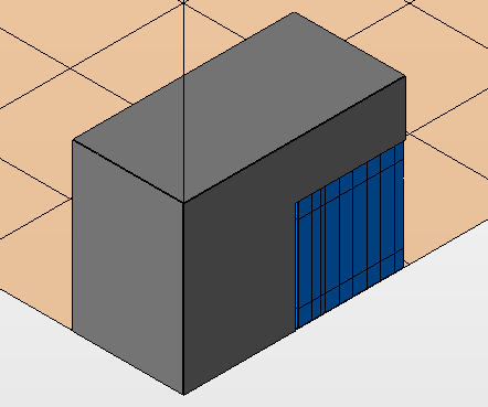
Add Parts. Figure 9.2 shows the imported geometry in the Netfabb environment.

Figure 9.2 Imported STL in Netfabb
- To add the support structures, from the top bar menu select . For Local Simulation to properly read the support structures, they must be box type fragment free structures with continuous polylines.
- Import the provided automated support script by clicking the Support Scripts tab near the center of the Enhanced Support Module window.
- Click
.
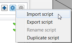
- In the Open File dialog, navigate back to the examples 09 folder (C:\Program Files\Autodesk\Autodesk Project Pan 2017\examples\09), select the file box_type_no_fragments.support and click Open.
- Near the center of the side panel, click the
Analysis tab, and then click the
Supportscript button at the bottom of this tab. A selection menu will appear, like the one shown below.
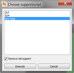
- Choose the box-type option, corresponding to the support script just imported, and click
Execute to generate the supports shown below.
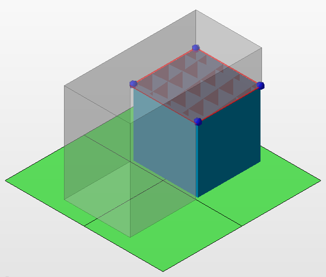
These supports will work, but are too coarse for this small build.
- To make the supports more visible, on the Analysis tab, select Tranparent part.
- Select the support structure with the mouse, then click the Edit tab.
- On the
Edit tab, expand the
Raster menu by clicking the + sign.
The Hatch distance is set to the default value of 2.50 mm.
- Click on the value to edit it, then reduce it by 50%: enter 1.25 in the value box and press Enter.
This action creates a much finer support structure.
- Click the
Analysis tab again and then click the
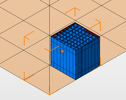
Apply support button at the bottom to finish creating the supports, which should resemble those below.
- To get a better view of the supports, hide the part by going to the
Parts tree and clicking the yellow eye icon beside the overhang value.
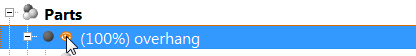
The supports should resemble the ones below.
- Inspect the supports by holding the right mouse button down while moving the mouse, or by using the saved view icons in the menu bar
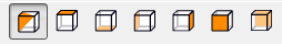 . Ensure there are no breaks in the contour or other defects.
Now the generated supports need to be sliced and output as a CLI file.
- Click on the supports to highlight them.
- On the
Extras menu, click
Slice Selected Parts.
A window pops up for slice control. The Start and Stop values are automatically generated from the support geometry by Netfabb.
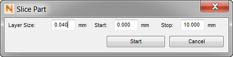
- Ensure the Layer Size is equal to the layer size in the PRM generation input files, 0.040 mm, then click Start.
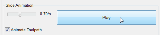
- In the control panel, click
Animate Toolpath, set a
Slice Animation speed over 10/s, and then click
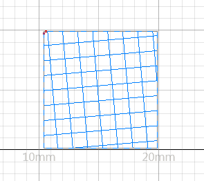
Play to have Netfabb play through the slices.
An example slice towards the center of the build is shown below.
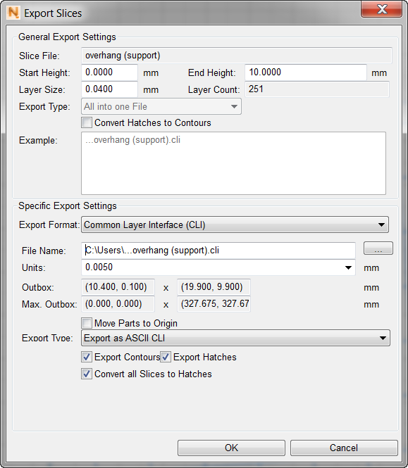
The final step is to output the slices as a CLI.
- From the top menu bar choose .
-
In the Export Slices dialog, review the File Name and save path. At the bottom of the dialog, select the three boxes, Export Contours, Export Hatches, and Convert all Slices to Hatches, then click OK to save the CLI file.