
Click to open the key dialog for configuring a simulation. Because some of the settings affect others, it is recommended that you set values in the sequence presented in the following procedure.
- On the Part tab, enter the Machine Model and Configuration.
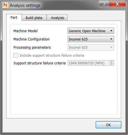
Selecting one of the Material Configuration defaults automatically selects the corresponding default PRM file. In the current Simulation Utility configuration, each material property has only a single generic PRM file, so results from using any of the various process parameter configurations will be identical.
If you want to select a custom PRM file, set the Machine Configuration to Custom, and select a file in the Processing parameters field. The custom option also allows you to input your own material properties for part-level powder bed simulations.
- On the Build Plate tab, select either to match the part material, or select a different material from the drop-down list.
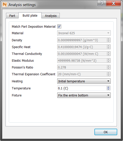 Note: Currently the Match Part Deposition Material option is not supported when using a custom PRM file; in this case, select the Custom option on the Material drop-down menu and manually input the properties.
 - Select the Heating option (none, initial temperature, or controlled temperature). Initial temperature implies build plate preheating, and controlled temperature implies constant build plate heating.
- Select a Fixture setting, either to fix the entire bottom of the build plate through the end of the simulation, or fix to the bottom and then add an additional time step to simulate release after cooling. The setting “fix to the bottom and release after cooling” simulates the effect of removing the bolts from the build plate.
- On the Analysis tab, optionally use the Deposition Multiplier to scale the timing between increments to account for building multiple parts on the build plate. For example if there are 12 identical parts on the build plate, and you want to simulate only 1 of the parts, enter a value of 12.
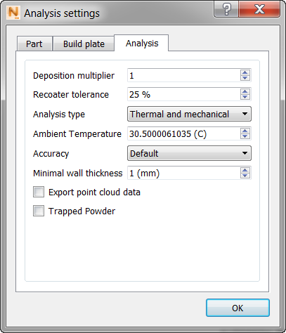
Enter the Recoater Tolerance, which is a measure of minimum required clearance between the previous build and the recoater blade, expressed as a percentage of the powder layer.
Also on the Analysis tab, enter Analysis Type (thermal, mechanical, or both), the Ambient Temperature (to improve accuracy of simulation results), and the degree of Accuracy (accurate, moderate, default, or fast), which controls the mesh density.
The minimal wall thickness should be set roughly equal to the thinnest section of the imported CAD geometry. This value determines the size of the smallest element in the auto-generated mesh. Use a higher value for a coarser, quicker mesh and a lower value for a more geometrically accurate mesh.
Check boxes:
- Export point cloud data: Select this to add to your results 3D point clouds of your solved simulation. In the results folder, the exported files will have .wrtu extensions, and will be numbered 1 and 2 or 1 to 3, as follows:
- After deposition is complete
- After removal from build plate
- After removal of support structures (if applicable)
- Trapped Powder: Select this to account for trapped powder in your simulation, which produces more accurate thermo-mechanical modeling.