In the Analysis tab, you can define if you want to show the part, show the support, show the platform and the marked downskin or hide them. It’s also possible to show the part and the support entities transparent (if you can’t see the transparent options, you might have a graphic card below OpenGL 3.3 – please check your computer and graphic card specifications).
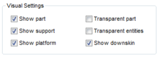
Visual settings in order to get a clear overview of part, platform and support structures.
Zoom into the Structures and Anchors
When you have selected a support entity, you can zoom to the next entity with the N-key or go back to the one before with B. In the List tab, it’s possible to set cuts for the selection automatically, so the selected entities are never hidden by other structures. You can also change the default zoom orientation in the settings menu. If you are watching the support structure from below, for example, and switch to the next part, the zoom orientation will automatically turn into isometric view. Therefore it is possible to change this default orientation to any possible perspective or to keep orientation.
 You can also zoom to the selected support by using the icon in the tool bar
In the support tool, you find the View tab. The cutting options here can be used as a viewing tool, similar the viewing functions in the default, repair and measure modules: move a bar until you see an outline on the model and click on one half of the little orange box on the left side of the bar. The model and its support will then be opened up and you can take a deeper look into the structures.
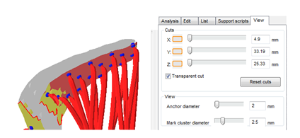
inner view of part and support via the cuts in the View tab.
Don’t forget to reset the cuts before you go back to editing the part. You can also vary the displayed size of the anchors: simply move the slider to the left or right. Mark cluster diameter lets you change the size of the mark cluster manual tool.
Supportvolume with lasersize shows you the real support module according to your lasersize. You can set the laser size under settings in the support module tab. This only applies for metal machines that use a laser of course.
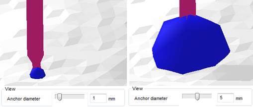
For easier handling, vary the size of the anchors with the Anchor diameter.
Edit Single Entities of the Support Structures
By opening the tray attached to this icon in the toolbar you can find different possibilities to edit single support entities. Changes will always be made to the currently selected entity. The menu can also be accessed through the context menu, by right clicking on the selected support entity.
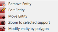
The different options for a single support entity
Edit Entity will open a dialogue where you can make various numerical changes to the different parameters of the structure. Move Entity allows you to enter a numeric value for precise movement of single structures.
Modify entity by polygon allows you to cut out parts of the entity. This feature is intended to be used with volume support. Just click on the entity to define at least 3 points which will describe your polygon. In the context area a 2D thumbnail of your part will be displayed, where you can see your current polygon and also the cuts you already performed.
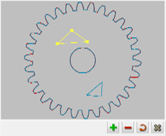
An example for a created polygon and the interaction buttons you get similar to the boolean operators.
Save Own Support Settings
Whenever you have defined settings that are perfect to your machine, you can save them as default settings and load them any time you need them. This saves you adjusting time.
Use the blue gearwheel next to your set and decide which set you want your settings to be saved to. You can also export the sets as an XML, for use on another computer for example.
It is also possible to define parameters in the program settings (in the Settings menu), which mostly affect the display of the support.
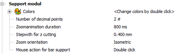
Display settings of the support in the program settings.
Here the step length for z cutting can be modified. Thus you can visualize single layers during production of the part. In the view tab it is possible to view the part in its different stages during the building process.