The project tree lists all parts and slices of a project in a way similar to a directory tree. There are several sections, such as Parts or Slices. Elements in the project tree can be sorted into groups, and they can have subordinate elements, such as Part Repair or Measuring. These are often connected to other modules.
Subordinate elements of groups or parts can be expanded or collapsed by clicking the Plus or Minus symbols at the branchings.
While working with Netfabb, you can always switch between the different sections, elements, and operations of the project by simply left-clicking them in the tree. For example, by clicking a sliced part in the Slices section, Netfabb will automatically switch to the Slice Commander and select the part you clicked. If you click a Part Repair entry, Netfabb will automatically switch to the Repair module of the respective part, and restore any previously conducted repair operations. That way you can conduct different operations and switch between them.
Next to the part name, a percentage value is displayed. This value specifies the level of detail with which the parts are rendered in the screen.
Clicking any parts or slices selects them. Multiple parts may be selected by holding Shift: This selects the one clicked second and any parts listed between this one and the one selected beforehand. Multiple selection of individual, non-contiguous parts is achieved similarly, but by holding Ctrl instead. The latter also allows to de-select parts from a multi-selection.
When a part is invalid (has inverted triangles or open triangle edges, for example), consists of more than one shell, or is hidden, its entry in the Project tree is marked accordingly. Damaged parts have an exclamation mark at the bottom right of the colored dot next to the part name. Parts with more than one shell have a small square at the top right of the dot. The color of the eye symbol indicates the visibility: Visible parts have an orange eye, hidden parts a grey one.
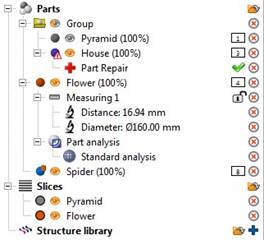
This project tree includes a group with the two parts Pyramid and House. The grey eye indicates that the pyramid is hidden. The warning sign for the house indicates that it is damaged. A repair has been opened
You can start certain operations in the project tree by moving elements into other directories by drag & drop. For example, by moving a part from Parts to Slices, a new, sliced part is created with certain parameters which you can enter in a dialog box.
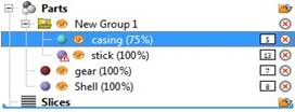
To slice a part, move it into the slices section with drag & drop. The blue bar indicates the place you drag an element to.
Further functions are available through the icons next to the name of entries. Double-clicking the folder icon calls an Open File dialog by which further parts may be added to the project. Double-clicking the colored dot opens a color picker to change the color of a part (This is for displaying in Netfabb only, it doesn't actually apply or change color information, even if its file format supports color). Double-clicking the red X symbol removes an object or function from the project. Single-clicking the eye icon toggles visibility of an object.
When certain features are active, other icons are added, such as a blue plus icon to add elements to the project or a green tick next to the repair section to apply the repair. The number tags are labels. They count up as parts are added. Their values stay for as long as the project exists, parts are not re-numbered when older parts are deleted.
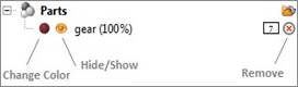
Icons in the project tree perform certain functions of the program.
Many more functions of the software are available in the project tree via context menus by right-clicking on objects.
Choose Create New Group from the context menu to gather multiple elements into subdirectories, helping you maintain order and organization in your project. Elements can be added or removed from groups by drag & drop. Groups can be created both in the Parts section and in the Slices section of the tree.
Using the
splitter handle
 allows
resizing the different panes like Project Tree, Tabsheet, or Viewing screen by
drag & drop. Though the splitter handle's context menu, you can toggle the display of
headers, or even undock some panes into separate windows (option
Locked must be unchecked); re-dock by grabbing the header (not the Windows title bar). Several
Docking Options are also available here.
allows
resizing the different panes like Project Tree, Tabsheet, or Viewing screen by
drag & drop. Though the splitter handle's context menu, you can toggle the display of
headers, or even undock some panes into separate windows (option
Locked must be unchecked); re-dock by grabbing the header (not the Windows title bar). Several
Docking Options are also available here.
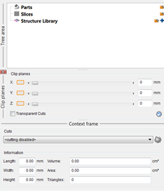
The headers display the names of the different areas in the project tree. To undock it into a different window make sure the Lock option is unchecked and drag it out into a new window.
The docking options in the context menu give you more options to customize the splitter, header and other elements
The docking options