The viewing screen occupies the biggest section of the user interface. It provides the three-dimensional visualization of a project, including parts and (optionally) the platform. In the bottom left is a coordinate system indicating the current perspective from which you see the project. It shows the X-, Y- and Z-axis as well as the three planes between those axes. The size of the planes in the program vary, depending on the current perspective, with planes in the background always displayed larger than those in the foreground. The size of those planes can be changed in the settings. If the used file format supports the display of colors and textures, these will be visualized in the viewing screen.
There are several intuitive ways to edit the view or performing simple tasks in the viewing screen. The viewing perspective is changed by holding the right mouse button and moving the mouse in the direction you want to turn the project visually.
You can also shift the view without changing the perspective, if you hold the central mouse button and move the mouse accordingly. If you do not have a central mouse button, for example on a laptop, hold Shift and the right mouse button.
To zoom in or out use the scroll button of your mouse. If you do not have a scroll button, hold Ctrl and the right mouse button and move the mouse up and down.
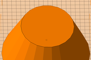
The moving and rotating of parts is also conducted by drag & drop. You can move a part by left-clicking on the little green square in the middle of a selected part, holding the button and moving the mouse. If more than one part or a group is selected, all selected elements are moved. Furthermore, selected parts can be rotated in the viewing screen by clicking on the green brackets around the part, holding the left mouse button and moving the mouse in the direction of the rotation.
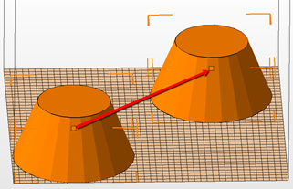
Use drag & drop to move parts.
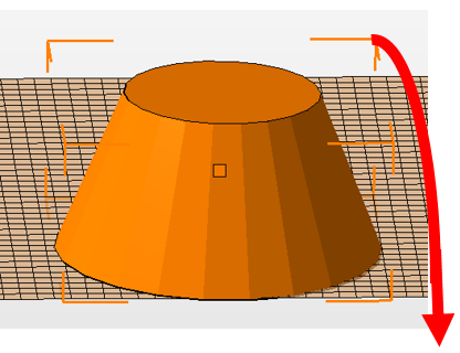
Use drag & drop on the orange brackets to rotate part.
Change perspective and zoom with right mouse button and scroll button.
Below the screen, the current mode is specified, indicating which intuitive operation can currently be conducted with the mouse (default: Move/Rotate). If you change the mode, for example to Align to Bottom Plane, other operations can be performed by the mouse (in this case a double-click on a surface of a part rotates the part to align that surface to the X-Y-plane).
Whenever operations are conducted that are performed in other modules, the viewing screen switches to special interfaces, for example to the repair screen, the slices screen, the measuring screen or the screen for Boolean Operations. Intuitive control elements such as zooming in and out, changing perspectives and shifting the view are the same as in the standard interface.
Left: The two-dimensional view on the slice of a part in the slice commander. Right: A damaged part in the repair module.