Simple cuts parallel to the main planes can be prepared in the standard interface, as all options can be found in the tabsheet. Parts can be cut in a right angle across the X-, Y- and Z-axes at specific coordinates, with a cutting plane parallel to the other two axes. By clicking on Execute cut, the Free Cut module is opened, with the same cutting plane in place. There, you can adjust further settings and execute the cut. If you have set cutting lines across more than one axis, you have to choose in a dialog which plane you want to insert. The split parts resulting from the cut are treated as own, separate parts.
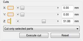
Cutting options in the tabsheet
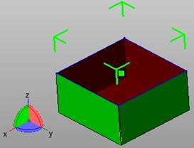
Cut across X-axis
The value of the axis, across which a cut shall be performed, can be set by a regulator or by manual insertion of a value. Additionally, you can set cutting planes with the mouse.
To set a cutting plane with the mouse, right-click on the orange box between the axis letter and the regulation bar and choose Set cut in the context menu. After you click on it, you can click on the part to set a cutting plane across the chosen axis, which runs through the point you clicked on. If you hold the left mouse button, a transparent plane is displayed as a preview. You can move it across the part by drag & drop. The plane is not inserted until you release the left mouse button.
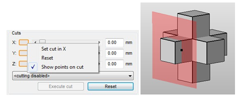
Left: Right-click on the orange box to set a cut with the mouse. Right: If you hold the left mouse button, a transparent cutting plane is displayed as preview to the cut. The plane moves across the part, if you move the mouse.
To illustrate and preview the result of a cut without actually performing it, all active cutting lines are shown. With default settings, the cutting line across the X-axis is red, the cutting line across the Y-axis is green and the cutting line across the Z-axis is blue. After a right-click on the field between the axis letter and the regulation bar, you can choose to show the corner points on the cutting line.
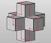
Visualized points on a cut
The buttons between the axis-letter and the regulation bar show you which components of the cut can be seen in the viewing screen. By clicking on that buttons, you can hide these components and show them again. The orange boxes to the left and right represent the display of sections of parts with lower and higher coordinates than the cut. Hiding these sections helps you to get an unobstructed view on the resulting split parts. The yellow line in the middle controls the display of the cutting line. If you click on it, it is hidden and shown again. A hidden cutting line is deactivated and cannot be transferred to the Free Cut module. It is shown and activated again automatically, if you change the coordinates for the axis.
These viewing functions can be combined freely and make the cutting function a powerful viewing tool, as you can see cross sections and the interior of parts. For example, you can scroll from top to bottom with the scroll bar of the Z-axis and hide the top section to see the horizontal cross sections of the part.
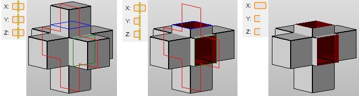
Cutting lines across all three axes with three different viewing options. First, everything is displayed. Second, sections before the cut across the Y-axis and after the cut across the Z-axis are hidden. Third, the cutting lines are hidden as well.
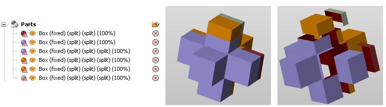
The resulting split parts of the cut above can be moved separately as own parts.
Reset sets back all cutting coordinates to zero and hides potential cutting lines. In the context menu of the axes (after right-clicking between the axis letter and the regulation bar) you can reset the cutting lines of single axes.
Cuts can be performed either for all parts or only for selected parts. Thus, all parts of a project could be affected by a cut. The setting you choose in this dropdown menu is adapted automatically in the Free Cut module.
After performing a cut, the cutting line of the axis which was selected for the cut is set back, the others remain. So, if you want to perform cuts across more than one axis, you can repeat the cutting process without the necessity of setting the second and third cutting line one by one. That way, one part is dissected into up to eight parts.