Surface Contact Parameters
Description: Defines the parameters for a surface contact region.
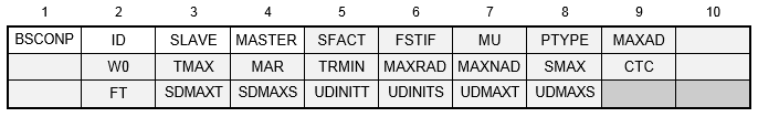
Format:
Example:

| Field | Definition | Type | Default | ||||||||||||
|---|---|---|---|---|---|---|---|---|---|---|---|---|---|---|---|
| ID | Contact region identification number. | Integer > 0 | Required | ||||||||||||
| SLAVE | Slave region identification number. | Integer > 0 | Required | ||||||||||||
| MASTER | Master region identification number. | Integer > 0 | Required | ||||||||||||
| SFACT | Stiffness scaling factor used to scale the penalty values determined automatically. See Remark 4. | Real > 0.0 | 1.0 | ||||||||||||
| FSTIF | Frictional stiffness for stick. See Remarks 5 and 12. | Real ≥ 0.0 | Model dependent | ||||||||||||
| MU | Coefficient of static friction. | Real ≥ 0.0 | 0.0 | ||||||||||||
| PTYPE | Penetration type. See Remarks 6 and 7.
|
1 ≤ Integer ≤ 11 | 1 | ||||||||||||
| MAXAD | Maximum activation distance. See Remark 8. | Real ≥ 0.0 or AUTO | See Remark 8 | ||||||||||||
| W0 | Penetration surface offset. See Remark 9. | Real | 0.0 | ||||||||||||
| TMAX | Maximum allowable penetration used in the adjustment of penalty values normal to the contact plane. A positive value activates the penalty value adjustment. See Remark 10. | Real ≥ 0.0 | See Remark 10 | ||||||||||||
| MAR | Maximum allowable adjustment ratio for adaptive penalty values K and FSTIF. See Remark 11. | Real > 1.0 | 100.0 | ||||||||||||
| TRMIN | Fraction of TMAX defining the lower bound for the allowable penetration. See Remark 12. | 0.0 ≤ Real ≤ 1.0 | 0.001 | ||||||||||||
| MAXRAD | Maximum radial activation distance. See Remark 13. | Real ≥ 0.0 | 0.0 | ||||||||||||
| MAXNAD | Maximum normal activation distance. See Remark 13. | Real ≥ 0.0 | 0.0 | ||||||||||||
| SMAX | Maximum allowable slip used in the adjustment of penalty values parallel to the contact plane (FSTIF). A positive value activates the penalty value adjustment. See Remark 14. | Real ≥ 0.0 | 0.0 | ||||||||||||
| CTC | Contact thermal conductance. See Remark 15. | Real ≥ 0.0 | ∞ | ||||||||||||
| FT | Failure theory. The following weld bond failure theories are allowed.
|
Character or blank | WFM | ||||||||||||
| SDMAXT | Tensile stress of the weld bonding material when damage initiates. See Remark 16. | Real ≥ 0.0 or blank | 0.0 | ||||||||||||
| SDMAXS | Shear stress of the weld bonding material when damage initiates. See Remark 16. | Real ≥ 0.0 or blank | 0.0 | ||||||||||||
| UDINITT | Separation normal to the master weld surface when bond damage initiates. See Remark 16. | Real ≥ 0.0 or blank | 0.0 | ||||||||||||
| UDINITS | Slip tangential to the master weld surface when bond damage initiates. See Remark 16. | Real ≥ 0.0 or blank | 0.0 | ||||||||||||
| UDMAXT | Separation normal to the master weld surface when bond damage results in complete failure. See Remark 16. | Real ≥ 0.0 or blank | 0.0 | ||||||||||||
| UDMAXS | Slip tangential to the master weld surface when bond damage results in complete failure. See Remark 16. | Real ≥ 0.0 or blank | 0.0 |
Remarks:
- Contact region identification number must be unique with respect to all other BCONP and BSCONP identification numbers.
- The SLAVE field defines the slave surface by referencing a BSSEG Bulk Data entry.
- The MASTER field defines the master surface by referencing a BSSEG Bulk Data entry.
- SFACT may be used to scale the penalty values that are determined automatically based on adjacent diagonal stiffness matrix coefficients. Additionally, penalty values calculated may be further scaled by the SLINEKSFACT model parameter (see Section 5,
Parameters, for more information on
SLINEKSFACT). The penalty value is then equal to
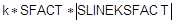 , where k is a value selected for each slave node based on the diagonal stiffness matrix coefficient and SFACT is specified in the SFACT field above. Note that the SLINEKSFACT value applies to all contact regions in the model. The use of a scale factor (SFACT or SLINEKSFACT) less than one is recommended when convergence problems arise and a value greater than one when excessive penetration occurs. Penalty values are normally recalculated every time there is a change in stiffness. However, if SLINEKSFACT is negative, penalty values are not recalculated. This setting is generally not recommended.
- The value of frictional stiffness should be chosen carefully. A method of choosing a value is to divide the expected frictional strength (MU * expected normal force) by reasonable value of the relative displacement before slip occurs. A large stiffness value may cause poor convergence, while too small a value may result in reduced accuracy. An alternative method is to specify the value of relative displacement using SMAX.
- For unsymmetric contact, only the penetration of the slave node into the master segments is checked. This may lead to the master nodes penetrating the slave segments. This error is reduced as the mesh density is increased. For symmetric penetration, both the slave and master nodes are check for penetration. This is accomplished by generating a slave node, master segment element using the MASTER surface for the slave nodes and the SLAVE surface for the master segments.
- Welded contact behavior is accomplished by selecting the unsymmetric or symmetric welded contact setting (3, 4, 9, 10, or 11). With either setting the element will behave the same in tension as in compression and will not slide. Note that for linear solutions with the LINEARCONTACT model parameter set to OFF, general contact will default to welded behavior (see Section 5, Parameters, for more information on LINEARCONTACT). Bi-directional sliding contact behavior is accomplished by selecting the unsymmetric or symmetric bi-directional contact setting (5 or 6). With either setting the element will act similar to a welded contact element in tension and compression, but will slide in-plane. Bi-directional sliding contact is available in all solutions. Rough contact behavior is accomplished by selecting the unsymmetric or symmetric rough contact setting (7 or 8). With either setting the element will act similar to a general contact element in tension and compression, but will not permit sliding in-plane. The offset weld setting (9 or 10) is intended for welded connections with significant separation between contact surfaces. Welded contact with a separation less than the value defined by the SLINEOFFSETTOL model parameter is automatically converted to an offset weld (see Section 5, Parameters, for more information on SLINEOFFSETTOL.)
- MAXAD may be used to prevent unnecessary generation of contact segments when little or no sliding is expected. Elements are only generated if the distance from any contact surface master node to the potential slave node is less than
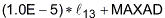 , where
 is the distance from node 1 to node 3 of the contact surface. Zero value of MAXAD is allowed. The default value is controlled by
SLINEMAXACTDIST parameter, which in turn defaults to 1.0E+30 for rough and general contact for nonlinear analysis types, and to AUTO for all other contact and analysis types. For all contact types except welded, the AUTO setting defines a MAXAD value for each element of the master surface equal to the maximum edge length of that element. For welded contact, the AUTO setting defines a MAXAD value for each element of the master surface equal to the maximum edge length of that element multiplied by 30.0*SLINEPOSTOL. The AUTO setting will restrict contact generation to adjacent elements, while the 1.0E+30 setting will generate contact to allow unlimited movement. The AUTO setting is recommended for optimal performance when little or no movement is expected, such as with bolted connections. Note that specifying AUTO for MAXAD is not the same as leaving the field blank or entering 0.0.
is the distance from node 1 to node 3 of the contact surface. Zero value of MAXAD is allowed. The default value is controlled by
SLINEMAXACTDIST parameter, which in turn defaults to 1.0E+30 for rough and general contact for nonlinear analysis types, and to AUTO for all other contact and analysis types. For all contact types except welded, the AUTO setting defines a MAXAD value for each element of the master surface equal to the maximum edge length of that element. For welded contact, the AUTO setting defines a MAXAD value for each element of the master surface equal to the maximum edge length of that element multiplied by 30.0*SLINEPOSTOL. The AUTO setting will restrict contact generation to adjacent elements, while the 1.0E+30 setting will generate contact to allow unlimited movement. The AUTO setting is recommended for optimal performance when little or no movement is expected, such as with bolted connections. Note that specifying AUTO for MAXAD is not the same as leaving the field blank or entering 0.0.
- The contact plane is defaulted to the xy-plane of the master nodes. A positive value of W0 offsets the contact plane in the element z-direction and results in a contact condition occurring when a slave node penetrates the offset plane.
- There are two methods for adaptive stiffness updates normal to the contact plane: proximity stiffness based and displacement based.
- When TMAX ≠ 0.0, the displacement based stiffness update method is selected. The value specified defines the allowable penetration of the slave node into the master surface. The recommended TMAX value is between 1% and 10% of the element thickness for plates or the equivalent thickness for other elements that are connected to the contact element.
- When TMAX = 0.0 (default), the update method selected is dependent on the SLINESLIDETYPE and SLINEMAXDISPTOL model parameter settings. When SLINESLIDETYPE is set to DYNAMIC, the proximity stiffness based update method is selected. When SLINESLIDETYPE is set to STATIC, the displacement based stiffness update method is selected where SLINEMAXDISPTOL defines the default TMAX value using

where Area is the total length of the master slide line. See Section 5, Parameters, for more information on SLINESLIDETYPE and SLINEMAXDISPTOL.
- TRMIN is used for the penalty value adjustment and defines the lower bound for the allowable penetration computed by TRMIN * TMAX. The penalty values are decreased if the penetration is below the lower bound.
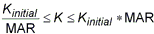
- The maximum adjustment ratio MAR defines the upper and lower bounds of the adjusted value by
- MAXRAD and MAXNAD are an alternative to MAXAD. If either one is set to a non-zero value, MAXAD will be ignored and MAXRAD and/or MAXNAD will be used instead. When MAXRAD is specified, elements are only generated if the element in-plane distance from any contact surface master node to the potential slave node is less than
 , where
is the distance from node 1 to node 3 of the contact surface. When MAXNAD is specified, elements are only generated if the element normal distance from any contact surface master node to the potential slave node is less than MAXNAD.
, where
is the distance from node 1 to node 3 of the contact surface. When MAXNAD is specified, elements are only generated if the element normal distance from any contact surface master node to the potential slave node is less than MAXNAD.
- There are two methods for adaptive stiffness updates parallel to the contact plane: proximity stiffness based and displacement based. If SMAX ≠ 0.0, the displacement based update method is selected. When SMAX = 0.0 (default), the proximity stiffness based update method is selected. If FSTIF is specified, it will be used as the penalty stiffness for stick when the proximity stiffness method is used. If SMAX ≠ 0.0, the FSTIF value will be adjusted internally to achieve the SMAX displacement specified.
- The contact thermal conductance CTC is defined as

where
 is the change in temperature between the slave node and average of the master nodes, and
q is the heat flux through the contact surface. Contact thermal conductance is only applicable in heat transfer solutions.
is the change in temperature between the slave node and average of the master nodes, and
q is the heat flux through the contact surface. Contact thermal conductance is only applicable in heat transfer solutions.
- There are two failure theories available for weld bond failure: WFM (Weld Failure Model) and CZM (Cohesive Zone Model). The WFM failure theory has two damage models used for modeling weld failure: stress-based and deformation-based. The usage of SDMAXi, UDINITi, and UDMAXi and default values are given below. One or both components of SDMAXi, UDINITi, or UDMAXi may be specified. SDMAXi values are ignored if UDINITi values are specified. Stress-based and deformation-based weld failure is only supported when PTYPE equals 3 or 4. Deformation-based weld failure is also supported when PTYPE is set to 9 or 10 (offset welded contact) or when PTYPE is set to 3 or 4 and reverts to 9 or 10 due to a separation greater than PARAM, SLINEOFFSETTOL. (See Section 5,
Parameters, for more information on
SLINEOFFSETTOL.) Stress-based weld failure is not supported for offset welded contact.
SDMAXi UDINITi UDMAXi WFM Damage Model and Default Values ✓ Stress-based damage model where UDINITi is calculated using SDMAXi and the equivalent weld stress and displacement from the first load increment. UDMAXi is the incremental deformation to failure after damage initiation and is set to 0.1% of the calculated UDINITi value. ✓ ✓ Stress-based damage model where UDINITi is calculated using SDMAXi and the equivalent weld stress and displacement from the first load increment. UDMAXi is the incremental deformation to failure after damage initiation. ✓ ✓ Deformation-based damage model. ✓ Deformation-based damage model where UDMAXi is defaulted to 2 * UDINITi. ✓ Deformation-based damage model where UDINITi is defaulted to 0.5 * UDMAXi. No damage model is used. The CZM failure theory requires either SDMAXT and UDMAXT or SDMAXS and UDMAXS to be specified. UDINITi are ignored. CZM is only supported when PTYPE equals 3 or 4 and is not supported for offset welded contact.