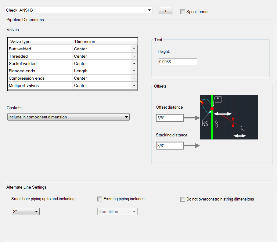
Specify the what items you want to be dimensioned and where you want them dimensioned to.
- On the ribbon, click Home tab
 Project panel
  Project Manager
  Project Setup.
 - In the Project Setup dialog box, expand Isometric DWG Settings. Click Dimensions.

- On the Dimensions pane, in the Iso Style list, select the iso style for which you want to set dimensions.
- Under Dimension Types, do the following
- In the Iso Theme list, select the iso theme (Default Piping or Small Bore Piping) for which you want the dimension type settings to apply.
- Select one or more of the dimension types check boxes.
- Under Dimension Type Options, for each component, select a dimension and select the appropriate check box. Only those check boxes are available that correspond to the check-box selection you made above the table. For example, if you selected String Dimensions above the table, only the String column check boxes are available. If you selected all three check boxes above the table, all check boxes in the table are available.
- Under General Dimension Options, do the following:
- Select or clear the Don't Overconstrain String Dimensions check box. Selecting this box removes the last string dimension in a linear piping segment when used with end-to-end dimensions to avoid overconstraining the dimensions.
- Under Gasket Handling, specify whether to dimension gaskets individually, not at all, or to include them with component dimensions.
- In the valve table, select Overall Length or Center as the dimension style for each valve type.
- Click OK.