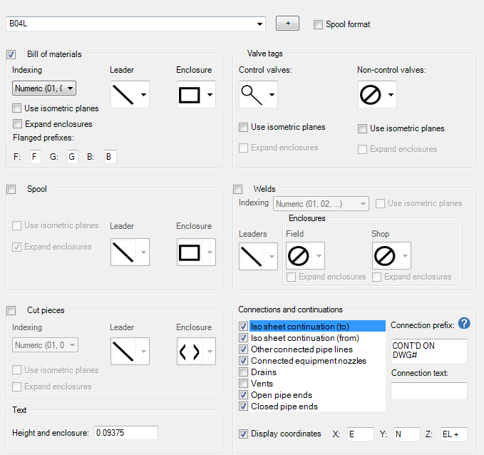
Specify how you want Iso objects to be annotated in the drawing.
- On the ribbon, click Home tab
 Project panel
  Project Manager
  Project Setup.
 - In the Project Setup dialog box, expand Isometric DWG Settings. Click Annotations.

- On the Annotations pane, in the Iso Style list, select an iso style.
- Under BOM Annotations, select the numbering style (alphabetic or numeric) and enclosure shape you want. Select the check box if you want to use a leader line.
- Under Cut Piece Annotations, select the numbering style (alphabetic or numeric) and enclosure shape you want. Select the check box if you want to use a leader line.
- Under Spool Annotations, select the numbering style (alphabetic or numeric) and enclosure shape you want. Select the check box if you want to use a leader line.
- Under End Connection Annotations, do the following:
- Select the item you want annotated.
- Select or clear the Show End Connection Annotation on Iso.
- Modify the connection text prefix as needed.
- Enter the connection text with property names in angled brackets.
- Select or clear the Append Coordinates and Elevation check box.
- Repeat these steps for each end connection you want annotated.
- Modify the coordinate prefixes as needed.
- Under Weld Annotations, select the numbering style (alphabetic or numeric) and enclosure shape you want. Select Shop, Field or both. Select the check box if you want to use a leader line.
- Under Valve Annotations, select check boxes for those items you want annotated with tag numbers, and select the style of annotation you prefer from the drop-down lists.
- Under Date, in the drop-down list, click a date format to display. To display the date in four digit year format, select the Use Four Digit Year Format check box.
- Click OK.