Next, we add the second bolt. Since the properties of the bolts are identical, we can place them in the same part. All of the data, except for the interior hole surfaces, is maintained from the previous bolt.
- Click and drag to draw a selection rectangle enclosing the hole near the top of the display.
- Click Add in the Interior hole surfaces(s) for one hole section.
- Deselect the Do not dismiss dialog after bolt generation check box. This is the last bolt we will add.
- Click OK. The Bolted Mesh Setup dialog box closes and the model should appear as shown in the following images. The second image shows the view zoomed in and slightly rotated, and the bolt selected for better visibility.
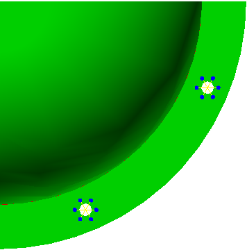
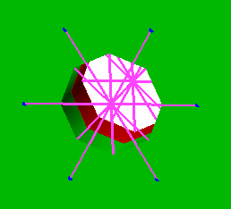
- Click OK. The Bolted Mesh Setup dialog box closes and the model should appear as shown in the following images. The second image shows the view zoomed in and slightly rotated, and the bolt selected for better visibility.