- Click the Right face of the ViewCube for a right side view of the model.
- Use
 View
View Navigate Zoom Window to zoom in on the area around the joint at the free end of the crank. Note: This command can also be accessed from the Navigation Bar, or you can roll the mouse wheel to zoom in.
 - With the
 Selection ShapePoint or Rectangle and
  Selection Select Vertices commands active, click and drag to draw a box enclosing the center of the joint.
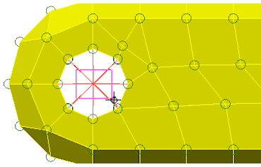
- Click
 Setup Constraints Prescribed Displacements.
 - Click the Rotation radio button
-
Type 1 in the Magnitude field. We will keep the default axis direction (Scalar X).
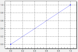
- Click the Curve button. The default curve ramps up the multiplier from 0 to 1 in 1 second. This is what we want. The curve within the dialog box should look like the image below.
- Click OK to exit the Multiplier Table Editor.
- Click the Data button.
- Type 1 in the first row of the Death Time column. Note: Prescribed displacements can be deactivated during a simulation event to allow free motion when necessary. Here, a death time of 1 second ensures that the displacement is active throughout the 1 second simulation event. In addition, deactivated prescribed displacements can be reactivated at a later time via the Rebirth Index and subsequent Birth Time entries. Simply add a row to the table for each rebirth of a prescribed displacement.
- Click OK to exit the Birth and Death Times table.
- Type 1 in the first row of the Death Time column.
- Click OK to accept the nodal prescribed displacement.
- With the center nodes of the joint still selected, Click
 Setup Constraints General Constraint.
 - Click Fixed and then clear the Rx check box. The joint is only free to rotate about the X-direction axis.
- Click OK.
- Click
 View Navigate Enclose (Fit All).