When you click the Options button in the Model Mesh Settings dialog and select the Surface icon, two tabs appear—General and Options. The Surface icon is present regardless of which radio button is selected in the Mesh type section of the Model Mesh Settings dialog.
General Tab
Mesh size Section:
Use the Size field in the Mesh size section to specify the size of the elements that will be generated.
- If the Percent of automatic option is selected in the Type drop-down box, you will be defining a percentage of the default mesh size. Either use the Coarse/Fine slider or numerically specify the percentage of the default mesh size in the Size field. The default mesh size is calculated based on the dimensions of the model or part.
- If the Absolute mesh size option is selected in the Type drop-down box, you will be specifying the approximate length of the sides of the elements created on the surface of the part. Enter the desired dimension in the Size field.
- The absolute mesh size that corresponds to the percent of automatic, and vice versa, is known only when the
Use automatic geometry-based mesh size function option (located in the Mesh
 Mesh 3D Mesh Settings Options Model
dialog) is deactivated. In this situation, switching between
Percent of automatic
and
Absolute mesh size
shows the percentage or dimension that corresponds to the prior
Type
option. Additionally, when using the
Absolute mesh size
mode, the slider is shown, and its position updated to reflect the specified dimension, but the slider is disabled.
Mesh 3D Mesh Settings Options Model
dialog) is deactivated. In this situation, switching between
Percent of automatic
and
Absolute mesh size
shows the percentage or dimension that corresponds to the prior
Type
option. Additionally, when using the
Absolute mesh size
mode, the slider is shown, and its position updated to reflect the specified dimension, but the slider is disabled.
- When the Use automatic geometry-based mesh size function option is activated, an initial mesh size of 1 is shown when you first switch from Percent of automatic to Absolute mesh size, regardless of the percent setting. Also, the Coarse/Fine slider is not shown.
- When the Use automatic geometry-based mesh size function option is activated, and the mesh size Type is set to Percent of automatic, the size of the mesh is different in each part (based on the sizes of the parts).
- When the Use automatic geometry-based mesh size function is deactivated, and the mesh size Type is set to Percent of automatic, the size of the mesh is the same in each part and is based on the size of the model.
For advice on specifying an adequate mesh size, go to Mesh Size Hints page.
Surface mesh retries upon failure Section
If a valid surface mesh cannot be created with the specified mesh size, the meshing algorithm will reduce the mesh size and attempt to mesh the model again. It will repeat this process until either a valid surface mesh is created or it performs the number of retries specified in the Number of retries field in the Retries section of the General tab. On the last retry, the mesher will complete the entire mesh except for the surfaces that it could not mesh correctly. The default value for this field is 6.
Each time a retry is performed, the mesh size is reduced by the factor specified in the Retry reduction factor field. In addition to reducing the mesh size, the following changes are tried (provided these changes result in a mesh that is smaller than the current settings:)
- If the
Use automatic geometry-based mesh size function (located on the Mesh Mesh 3D Mesh Settings Options Model dialog box) is activated, then the first attempt uses the default mesh size times the
Retry reduction factor. The default mesh size is defined as the mesh size of 100% without using the Use automatic geometry-based mesh size function.
- Retry 1: Curvature of edge curve set to 45 degrees
- Retry 2: Minimum adjacent surface curvature set to 30 degrees
- Retry 3: Maximum adjacent surface curvature set to 30 degrees
- Retry 4: Minimum adjacent surface curvature set to 30 degrees and activate Limit adjacent mesh size
- Retry 5: Maximum adjacent surface curvature set to 30 degrees and activate Limit adjacent mesh size
See Controlling the Number of Elements Along Curved Edges below for a description of each of these parameters.
Additional Options
Generate 2nd order elements: This option controls the shape of elements with midside nodes. This option has no effect on models or parts without midside nodes. The behavior is as follows:
- Deactivated: Midside nodes are created at the midpoint between the two corner nodes [see figure (a)]. Thus, all sides of the elements are straight regardless of the CAD geometry.
- Activated: Midside nodes are created on the surface of the CAD model [see figure (b)]. The edge of the element is represented by a quadratic equation and conforms more closely to curved surfaces. However, if the mesh is coarse relative to the radius of curvature, it is possible to produce highly distorted elements when this option is used [see figure (c)]. In such cases, the midside nodes on the distorted element are changed to create a straight, undistorted element. Thus, you may see some elements that apparently do not follow the surface of the CAD model even though the
Generate 2nd order elements
option is used. If it is important for these distorted elements to follow the surface, use one of the options for local mesh refinement (refinement point, edge curve refinement, and so on) to get a smaller mesh on the highly curved surfaces.
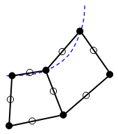
(a) Without the option, midside nodes do not follow the CAD surface. They are located at the midpoint between the corners of the element.
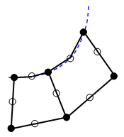
(b) With the option, midside nodes follow the CAD surface. This results in a more accurate representation of the geometry.
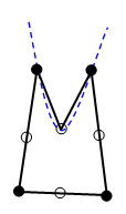
(c) If the mesh size is coarse compared to the curvature, a distorted element can occur. The mesher will make this element straight to avoid the distortion.
Use Delaunay+AFT mesher: This option is available for solid meshes only (not plate/shell or midplane), and only when using the Virtual CAD mesh engine (Mesh Mesh Use VCAD enabled). This mesher couples Delaunay triangulation algorithms with the Advancing Front Technique (AFT). For some models, this technology may be more robust (better handling problematic meshing scenarios) relative to the default VCAD mesher. If you encounter meshing problems, or if you are not happy with the quality of a mesh, try the
Use Delaunay+AFT mesher
option. Use whichever method that produces the best overall meshing results.
Options Tab
Mesh 3D Mesh Settings Options Model
dialog) is deactivated. Otherwise, the following controls are disabled.
Control the number of elements along curved features
Feature curve splitting angle: The value in this field controls how many elements are generated along curves in the feature lines. A smaller angle results in more elements created along the feature curves.
Edge curve refinement Section
Angle (1-90 degrees): The value in this field controls how the elements are created along curved edges and the adjacent surfaces. How this value is used is determined by the option selected in the Mode drop-down box.
Mode: Choose one of the following edge curve refinement options:
- None: No refinement is performed on the curved edges or surfaces of the selected parts.
- Curvature of edge curve: The specified Angle is used as the average angle between the elements created along the edges or curved surfaces. This option tends to leave a coarser mesh along the interior portion of a curved surface than near the edges.
- Minimum adjacent surface curvature: The specified Angle is used as the minimum angle between two adjacent element faces on curved surfaces. This option usually produces a more uniform mesh across the curved surfaces than the Curvature of edge curve option does. It also creates fewer elements than the Maximum adjacent surface curvature option does.
- Maximum adjacent surface curvature: The specified angle is used as the maximum angle between two adjacent element faces on curved surfaces. This option usually produces a more uniform mesh across the curved surfaces than the Curvature of edge curve option does. It also, among the four Mode options, typically creates the greatest number of elements along the curved surfaces.
Limit adjacent mesh size: When activated, two additional controls on the mesh size are imposed for mesh lines along features of the solid model. (The mesh lines on the interior of the surface are not controlled by this option, but they are controlled by the other options.) The additional controls are as follows:
- The ratio of the mesh size for two adjacent elements must be less than the user-entered value. Acceptable values are between 1 (all edge lines the same length) and 10 (rapid growth). You can use this option to produce more gradual mesh size transitions along surfaces adjacent to an edge curve. Therefore, edge curve refinement will not produce abrupt element size changes near short edge curve segments. See figure (a).
- The deviation of the mesh line from the theoretical curved edge is limited. In some situations, this feature creates more elements than would be implied by the
Angle
for the edge curve refinement. See figure (b).
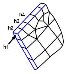
(a) The feature line through the thickness of the part (h1, at arrow) creates the smallest mesh size in this portion of the model. The adjacent mesh lines along the features (blue lines) grow geometrically so that each element is a maximum of X times larger than the previous. For example, if the user-entered a value of 1.3, then h2/h1<=1.3, h3/h2<=1.3, and so on.
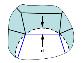
(b) The mesh around a hole deviates from the true surface by some distance d. (The lines on the features of the part are shown in blue; the theoretical hole is shown as a dashed circle.) If the deviation with the specified mesh size and other parameters is larger than allowed by the option, the mesh size will be reduced along the feature, thereby reducing the deviation.
Splitting quadrangles into triangles Section
Fold angle is greater than: The value in this field determines which quadrilateral element faces are divided into triangular faces based on the minimum fold angle (warp angle) of the quadrilateral. If the minimum fold angle of a quadrilateral face is greater than the value specified in this field, that face is divided into two triangular faces. The fold angle of a quadrilateral is the difference between the planar normals of the two triangles that form the warped quadrilateral. A flat quadrilateral has a fold angle of zero.
Node angle is greater than: The value in this field determines which quadrilateral element faces are divided into triangular faces based on the internal node angles of the quadrilateral. If the node angle is greater than the value specified in this field, that face is split into two triangular faces by adding a line that bisects the greatest node angle in the element face.