Use the
Mesh Mesh 3D Mesh Settings dialog box to mesh a CAD solid model in the FEA Editor environment. It sets the mesh settings for all the parts in the model. An identical screen appears when you specify the mesh settings for a single part in the model. (Select a part or multiple parts in the browser (tree view), right-click, and select
CAD Mesh Options Part.)
Mesh 3D Mesh Settings dialog box to mesh a CAD solid model in the FEA Editor environment. It sets the mesh settings for all the parts in the model. An identical screen appears when you specify the mesh settings for a single part in the model. (Select a part or multiple parts in the browser (tree view), right-click, and select
CAD Mesh Options Part.)
Mesh type section
Note that the mesh type will default automatically to Solid when importing CAD solid data and to Plate/shell when importing CAD surface data. It is also possible to define the mesh type on a per-part basis, overriding the global setting. When importing a CAD assembly with a mixture of solid and surface parts, the global mesh type will be set automatically based on the most prevalent type of part—Solid for a majority of solid CAD parts and Plate/shell for a majority of surface CAD parts. The less prevalent mesh type will be defined on a per-part basis using part mesh settings as an override of the global settings.
- Solid: Selected parts are meshed with solid elements (brick or tetrahedral).
- Midplane: Select if the selected parts are solid parts but will be collapsed to the midplane of the solid parts. After creating the midplane mesh, the average thickness of the plate elements is automatically used as the thickness for each surface. To use a specific value (for either the entire part or different surfaces within the part), clear the Use mid-plane mesh thickness check box in the Element Definition screen for the part.
-
Plate/shell: Select if the selected parts are surfaces for example, have no modeled thickness.
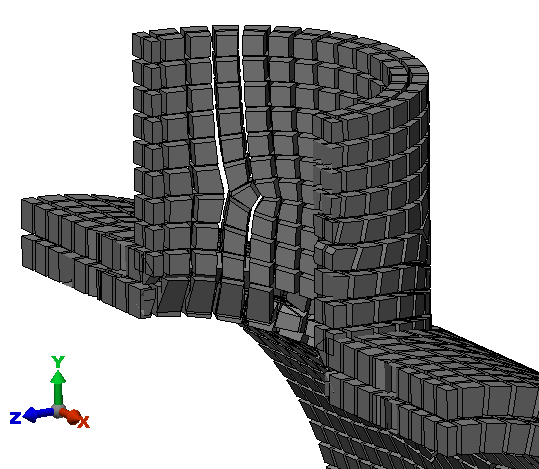
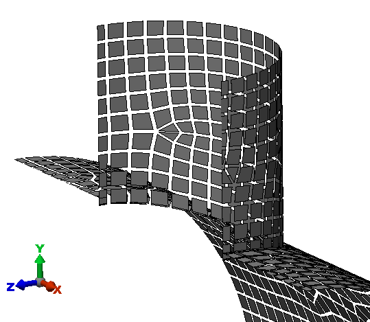
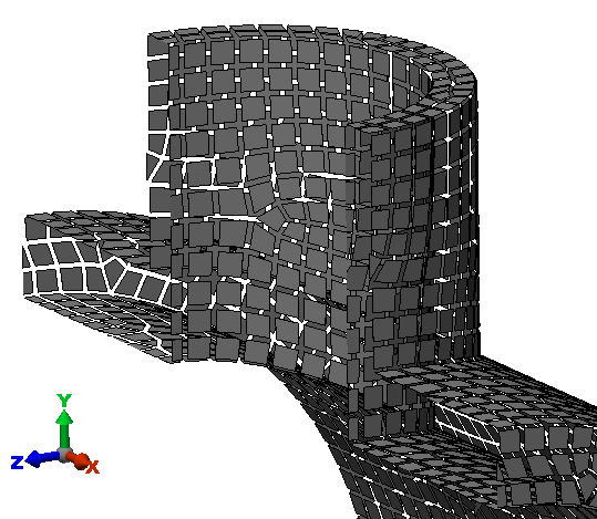
The difference between the three types of mesh (solid, midplane, and plate/shell) are demonstrated in the following images of two intersecting pipes. The figures show the model sliced in half, and the elements are shrunk to reveal the elements.
- Options: You can specify further mesh settings for the selected parts.
Examples of Each Mesh Type
The examples that follow demonstrate the difference in meshing behavior for the three mesh type settings based on the same CAD part data in all three cases.
Solid mesh: The volume between the inside surface and the outside surface of the CAD model is filled with brick elements. The thickness does not need to be entered. It is based on the mesh.
Midplane mesh: The inside surface and the outside surface of the CAD model are collapsed to the midplane location, and the mesh is created at the midplane. The thickness of the solid is represented by entering a numerical value (in the Element Definition) for the thickness of the elements. (The elements can be any type of area elements, such as plate elements or membrane elements.)
Plate/shell mesh: All surfaces of the CAD model, the inside surface and the outside surface, are meshed. The thickness of each element is represented by entering a numerical value (in the Element Definition). Unless you intended to create a double-walled vessel, this type of mesh is incorrect for this example CAD model. In this analysis, the two surfaces can move independently and pass through each other.
Control the mesh size
This slider in the Mesh size section controls the size of the mesh on the selected parts relative to the default size which is calculated based on the model dimensions.
Create matched mesh between parts option
This option is activated by default, and it instructs the program to match the mesh wherever two parts are touching each other. That is, each node along the contact surface of one part is coincident with the corresponding node on the mating part. In addition to the location of this option at the top-level of the
Model Mesh Settings
dialog, it can also be accessed under (Mesh Mesh 3D Mesh Settings Options Mesh Matching. You can activate of deactivate the option from either location; the options are linked and remain in sync.
A matched mesh is the easiest and most direct way to bond adjacent parts. Matching meshes are also required for surface contact in linear analyses solved using the native SimMech processor. However, there are some situations where generating an unmatched (non-conformal) mesh may be advantageous. For example:
- For MES or nonlinear static analyses with general surface-to-surface contact, the best performance and results are obtained when the meshes do not match between parts (non-conformal mesh). In nonlinear solutions contact is detected between a node on one part and an element face on the adjacent part. When the nodes are matched, the contact solution can oscillate between the element faces around each node, making convergence difficult.
- For large or complex assemblies, or assemblies in which the part size varies drastically, successfully matching the meshes of all of the parts can be problematic. The mesh can fail for some parts, or the surface mesh may be distorted near part intersections.
When you deactivate the
Create matched mesh between parts option, two additional actions take place automatically. Within the Mesh Matching settings (Mesh Mesh 3D Mesh Settings Options Mesh Matching), in the
Virtual imprinting section, the following options are also deactivated:
- Between parts
- Within a part
Virtual imprinting causes a smaller a CAD surface to be imprinted on a mating CAD surface so that meshes can easily be matched along surface/edge intersections. So, to prevent mesh matching, this option should also be disabled when you deactivate the Create matched mesh between parts option. The software performs this action for you automatically
See the Mesh Matching page for additional information.
Defaults button
Access the Meshing Option Defaults dialog. Two actions are available:
- Reset these options to system defaults: To undo your changes and restore the system default mesh settings.
- Make these options the system defaults: To redefine the system defaults to match your current mesh settings. Use this option for convenience when you frequently want to make the same overrides to the original default settings. In other words, you can make the settings that you use most frequently the system default mesh settings.
Click OK to complete the selected action.
Generate mesh button
The model is meshed with the current settings. This button will only be available if you are specifying the settings for the entire model.