This page concerns the friction parameters for general surface-to-surface contact in nonlinear simulations run using the native Simulation Mechanical (SimMech) solver. These parameters are located in the Friction tab of the Contact Options dialog. This tab is only visible when you activate the Include friction option under the General tab.
In frictionless contact, the element stiffness matrices are symmetric. Once friction is involved, the matrix becomes asymmetric. Using an asymmetric solver is computationally more expensive than using a symmetric solver. For the sake of efficiency, MES enforces symmetry of element stiffness so that the symmetric solver can be used for frictional contact.
When frictional contact is considered in the analysis, the solution process becomes highly vulnerable from the sliding process. Once the contact surfaces start sliding, the equilibrium state before the sliding is no longer valid and the processor must try to find a new equilibrium state during the solution process. Furthermore, poor convergence is possible due to the symmetry approximation. Each of the available friction law options attempts to control the solution instability in a different manner.
Select the desired Friction law: from the drop-down menu at the top of the Friction tab. There are three choices available for nonlinear surface-to-surface contact in Simulation Mechanical:
- Modified Coulomb friction
- Coulomb with viscous friction
- Smooth Coulomb friction
Each of these friction laws, and the parameters that apply to them, are discussed in the subsections that follow.
Modified Coulomb friction
This friction law uses the classical friction algorithm: Coulomb friction. In the basic Coulomb friction model, two contact surfaces can resist shear stress up to a certain amount, determined from friction coefficients and normal contact pressure, before they experience relative sliding motion. The Coulomb friction model is defined as: τ = μP, where μ is the friction coefficient and P is the normal contact pressure. You must define the following three parameters when using the Modified Coulomb friction law:
- Static friction coefficient (μs)
- Slicing friction coefficient (μd)
- Tangential stiffness ratio
Ideally, once the shear stress exceeds μsP, obtained from the Static friction coefficient input, the two surfaces start sliding. Additionally, the shear stress becomes μdP, where the Sliding friction coefficient value is used.
The ideal situation (no motion until the shear stress exceeds the static value) is difficult to achieve numerically, as described in Figure 1. Thus, a Tangential stiffness ratio is defined when using this friction law. The Tangential stiffness ratio is the ratio of the tangential contact stiffness (Kt) to the contact stiffness in the normal direction (K), which is defined under the Advanced tab. (See the Advanced Tab section on this page.) A larger tangential stiffness results in better accuracy but at the expense of requiring more iterations. A smaller tangential stiffness provides better convergence (shorter runtime) with the possibility of reduced accuracy. The recommend value is in the range of 0.01 to 1. As the static friction coefficient becomes larger, a smaller tangential stiffness ratio is recommended.
|
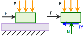
(a) Model and free body diagram of top block. The applied force F is ramped-up over time until it exceeds the static friction force. |
|
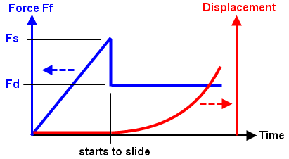
(b) Plot of friction force Ff versus time (blue curve) and displacement versus time (red curve). Until the friction force Ff reaches the limit of static friction (Fs = μs * N), there is no motion of the part. Once the static friction is exceeded, the friction force Ff drops from Fs to Fd (= μd * N), and the part begins to accelerate. |
|
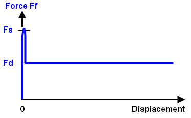
(c) The graphs in (b) are combined to show the friction force versus displacement. Ideally, there is zero displacement until the friction force reaches Fs, and then sliding begins. Numerically, this is difficult to achieve since any displacement other than zero implies a friction force of Fd. |
|
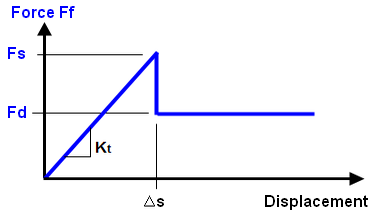
(d) To avoid the numerical instability in (c), the part is allowed to displace a small amount (Δs) while the friction force is less than the static limit (Fs). The amount of motion is controlled by the tangential stiffness (Kt = Fs/Δs). Smaller values of Kt allow the part to displace a larger amount before it starts to slide and are easier to converge, while larger values of Kt (steeper slope) allow less displacement before sliding and are more difficult to converge. The tangential stiffness is calculated by Tangential Stiffness ratio x stiffness in the normal direction. |
| Figure 1: Tangential Stiffness for Modified Coulomb friction |
Coulomb with viscous friction
Unlike the modified Coulomb friction law, static and dynamic coefficients of friction are not both considered in the Coulomb with viscous friction law. In the Modified Coulomb friction law, a relatively high force is required to overcome static friction and initiate motion. Once sliding begins, the friction force decreases because the sliding friction coefficient is smaller than the static coefficient. Thus, there is a force discontinuity due to the abrupt change in the friction force. For the Coulomb with viscous friction law, there is no friction force discontinuity when sliding begins. Instead, the friction force gradually increases as the sliding velocity increases.
For the Coulomb with viscous friction option, you must define two parameters:
- Sliding friction coefficient (Fd): This is also referred to as the dynamic friction coefficient. It is the ratio of the tangential force required to maintain relative motion and the normal force between the contacting parts. For example, if it takes 15N of tangential force to keep a block sliding along an adjacent part, and the normal contact force between them is 100N, then the sliding friction coefficient is 15N / 100N = 0.15. For the purpose of this friction law, you should base the sliding friction coefficient on relatively low-speed sliding.
- Viscous friction coefficient (νf): This is the slope of the friction force versus sliding velocity curve. As is true for all viscous effects, the force required to overcome viscous effects is proportional to the speed.
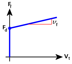
Figure 2: Friction Force versus Sliding Velocity (Coulomb with Viscous Friction)
In Figure 2, the friction force (Ff) curve is defined as follows:
Ff = Fd + νf · Vt
where
Fd is the dynamic (sliding) friction force,
νf is the viscous friction coefficient, and
Vt is the tangential (sliding) velocity between the two parts.
If νf = 0, then Ff = Fd
Smooth Coulomb friction
Like the Coulomb with viscous friction law, the Smooth Coulomb friction law only considers the sliding friction coefficient. This eliminates the friction force discontinuity that occurs between the static and sliding conditions when using the Modified Coulomb friction law. The transition between static and sliding conditions is further stabilized by the inclusion of a smooth transition factor (Φ).
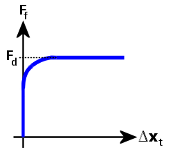
Figure 3: Friction Force versus Tangential Relative Displacement (Smooth Coulomb Friction)
In Figure 3, the friction force (Ff) curve is defined as follows:
Ff = Fd · Φ, and
Φ = tanh(3 · Δxt / δ)
where
Fd is the dynamic (sliding) friction force.
Φ is a transition factor, which makes the friction force smoothly approach zero as the tangential relative displacement approaches zero. Similarly, it makes the friction force smoothly approach the dynamic friction force as the tangential relative displacement increases.
Δxt is the tangential relative displacement, and
δ is a tolerance that is calculated based on the contact stiffness and dynamic friction force.