This topic details the options for general surface-to-surface contact in nonlinear analyses that are run using the native SimMech solver. To access these options, double-click an explicitly defined Surface contact pair heading in the browser. You can also select one or more surface contact pair headings in the browser, right-click, and choose Edit Settings from the context menu. Then, choose SimMech contact options from the drop-down menu at the top of the Contact Options dialog, if it is not already selected.
The nonlinear contact options are divided among four different tabs within the Contact Options dialog. In addition, contact updating parameters are defined within the General Contact Settings dialog. (See the General Contact Settings (Nonlinear) page.) For your convenience, a Description field is provided at the bottom of the Contact Options dialog. Any text entered within this field becomes the description displayed in the browser for the current contact pair.
General Tab
Contact method: Select one of the following options from the drop-down menu:
- Surface contact: This options prevents contact surfaces from penetrating through each other but allows them to separate freely or to slide relative to each other. Optional friction effects are supported for this contact method.
- Sliding contact / no bouncing: This option prevents contact surfaces from penetrating through each other but allows them to slide relative to each other. However, once the two surfaces come into contact, they cannot separate from each other. This is sometimes referred to as sticky contact. Optional friction effects are supported for this contact method.
- Tied contact: This option bonds the two surfaces together when they are within a specified distance from each other, preventing penetration, separation, and sliding. If the distance between the surfaces is greater than the specified distance, contact is not considered. Tied contact is useful for creating a bonded connection without having to generate matching meshes between the parts. Activating this option causes the
Tied tab to appear within the
Contact Options
dialog (see the
Tied Tab
section on this page). An analysis using this contact method will not be as fast as an analysis where the nodes on the surfaces are matched.
Note: Only the three translations of the nodes (Tx, Ty, Tz) on the surfaces are connected together; the rotations are not connected. Thus, in an arrangement of shell elements projecting out from the face of a brick part - like a cantilever beam made of shells - the shell part will be free to rotate at the brick support if only tied contact is used between the shell and bricks.
Include friction: Activate this option to include friction force effects at the surface contact interface. Activating this option causes the Friction tab to appear within the Contact Options dialog. Friction is supported for the Surface contact and Sliding contact / no bouncing contact methods.
Include sliding: Permit relative sliding along the contact interface. This option is deactivated by default and cannot be changed when you set the Contact method to Surface contact. Include sliding is activated by default when you choose the Sliding contact / no bouncing method, but you can deactivate it. When you do, surfaces cannot penetrate, slide, or separate once they come into contact. That is, the surfaces can move independently when they are not initially in contact but behave as if they are Tied once they come into contact. The Include sliding option is not applicable to the Tied contact method.
Friction Tab
This tab is only visible when you activate the Include friction option under the General tab. Please see the Friction Tab page for details concerning the available friction laws and associated parameters.
Tied Tab
This tab is only visible when you choose set the Contact method under the General tab to Tied contact.
Tied contact initial interference: If this check box is not activated, the initial distance between the surfaces is used as the contact distance. If this check box is activated, the contact interaction distance must be specified in the Tied contact tolerance field.
Tied contact tolerance: This field is only available when the Tied contact initial interference option is activated. Using the current model length unit, specify the distance between surfaces within which tied contact will be enforced.
Shell Tab
This tab only appears if one or both of the parts in the contact pair are comprised of shell or membrane elements. Select the side of the shells from which you want to detect contact. (The top side is the side opposite of the element normal point defined in the Element Definition dialog.) Contact only occurs when the contacting body approaches from the designated side. For example, if you indicate that contact occurs at the top of the shell, then contact occurs with the second body is moving in the direction from the top toward the bottom. No contact is made if the second body is moving from the bottom toward the top. Another way to visualize this is as follows: the second object makes contact with the chosen side (either the top or bottom) only when it is approaching from outside the shell. It will not detect contact if it passes through the shell to reach the chosen side. See Figure 1.
There is one option for the primary part and one for the secondary part:
Contact side for primary part: Choose Top or Bottom from the drop-down menu to specify the contact side of the primary part.
Contact side for secondary part: Choose Top or Bottom from the drop-down menu to specify the contact side of the secondary part.
Each of the above options is only active when the Element Type is defined as Shell for the associated part.
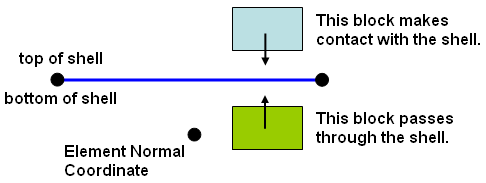
Figure 1: Two Blocks Defined to Contact the Top of the Shell
Beam Tab
This tab only appears if one of the parts in the contact pair is comprised of line elements (beam, truss, spring, pipe). Contact involving line elements is only detected when the node on a line element tries to penetrate the surface of a solid or planar element. Therefore, the solid or planar elements must belong to the primary part/surface, and the line elements must belong to the secondary part. Choose one of the following two options:
- Nodes make contact only at the ends of elements: Ignore all nodes along the length of a span of line elements except for the endpoints.
- Nodes make contact all along the line element: Contact can occur at any node belonging to the line element part.
For example, the bristles on a toothbrush made from beam elements only need to have contact between the nodes on the end of the bristles and the teeth. Only the nodes at the free ends of line elements would be used (first option). But a safety net made from truss elements needs to detect contact between all nodes on the net and the falling object (second option).
Advanced Tab
Please see the Advanced Tab page for details concerning the available parameters within this tab.
Geometry Tab
Please see the Geometry Tab page for details concerning the available parameters within this tab.
Time-step Tab
Invoke automatic time-step reduction method: If this option is activated, the time step is reduced automatically once the two surfaces are closer than the specified distance. The advantage of this reduction is to anticipate that a smaller time step will be required when contact occurs and to reduce the time increment before it occurs.
Minimum time-step size for contact: The time step size is reduced at least to the value specified in this field when the contacting parts are within the specified Target distance for time-step reduction. Often, the time step is reduced even further, since time step divisions occur whenever convergence difficulty is encountered. If the Minimum time-step size for contact is set to zero, then the processor uses the current time step divided by 10.
Target distance for time-step reduction: Specify the distance between the contacting parts/surfaces at which time step reduction should occur. (Note that the Target distance for time-step reduction is compared to the separation of the actual surfaces, without taking the contact distance into account.)
If the Invoke automatic time-step reduction method check box is not activated, the time-step will be reduced (by division) only if necessary to satisfy the equilibrium and contact convergence criteria.