This command is accessed from the Design panel of the Draw tab.
The general purpose of the Centroid Creator command is to calculate the centroid location of a set of surfaces or edges and to place a construction vertex at this centroid. Optionally, you can connect the nodes on the selected surfaces or edges to the centroid with line elements ("spokes"). Thirdly, you can specify a secondary set of surfaces or edges, create a second construction vertex, create a second set of spokes, and connect the two centroids together with a line element. So, there are three levels of Centroid Creator functionality:
- Level 1: Create a construction vertex at the centroid of a set of selected surfaces or edges.
- Level 2: Same as Level 1, plus create line elements between the centroid point and all vertices associated with the selected surfaces or edges. This level is similar to the action of the Joint command when using the Universal Joint option.
- Level 3: Create two centroids and two sets of spokes. (Each centroid and set of spokes is associated with separate sets of selected surfaces or edges.) Additionally, connect the two centroids together with a single line element.
The Centroid Creator provides a convenient means of connecting two areas of a model together with line elements. In one operation, it provides the same results as using the Joint command twice and the Line command once. This command can also be used to apply a load or a constraint at the centroid of selected model geometry and to connect the load or constraint to the model.
Any type of line element can be specified for centroid creator geometry:
- For linear structural analyses the line elements can be beam, truss, spring, or gap elements.
- For nonlinear structural analyses, the line elements can be truss, beam, spring, pipe, contact, general contact, actuator, dashpot, or slider elements. In the case of a slider, the line must be divided into two segments to create an intermediate (sliding) node, at which you would presumably attach another part.
- You can also use this tool to create thermal rod element connections between parts in a Heat Transfer analysis.
Centroid Creator Usage Example
Consider a long channel used in a structure, and the interaction of the bolted connections at each end are to be studied in detail. So a CAD model of the beam, bolts, and connection is created. If the span of the channel is not of interest in the analysis, it can be replaced with a few beam elements to greatly reduce the size of the analysis. The Centroid Calculator automates the process of connecting each node on the cut end of the channel to the centroid, and then connecting the two centroids. See the following figure.
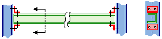
Figure 1(a): Full CAD model in which the entire horizontal channel is modeled with brick elements.
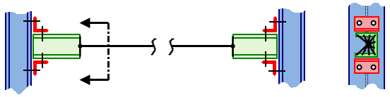
Figure 1(b): More efficient model in which a portion of the horizontal channel is modeled with beam elements. Only the end connection portion, requiring the detail provided by brick elements, is represented in the CAD model.
Steps for Using the Centroid Creator Command
- Although not mandatory, the recommended workflow is to mesh the model prior to using the Centroid Creator whenever you will be adding spokes. In this way, the spokes are generated immediately upon completing the command.
- Click
Draw
 Design Centroid Creator.
- Select one or more surfaces or edges.
- Populate the
Primary Centroid Geometry - Set 1 box by clicking
Add. The selected entities are listed in the box.
Note: You can also reverse the order of steps 1 and 2, in which case you can skip step 3. When the surfaces or edges are preselected, they appear in the Primary Centroid Geometry - Set 1 box as soon as you start the Centroid Creator command.
- To add lines connecting the surfaces or edges to the centroid point continue to the next step. Otherwise, to only create a construction vertex at the centroid, skip to step 11.
- Activate the Connect centroid to geometry with "spokes" option so that lines will be generated between the selected surfaces or edges and the construction vertex at the centroid point. Note that the default Centroid options selection is Create a centroid on a single selection set.
- Specify the desired
Part, Surface, and
Line attributes in the
Primary Spokes section.
- To select a separate set of surfaces or edges (secondary centroid), create the secondary spokes, and connect the two centroids with a line element, continue to the next step. Otherwise, to only create one centroid and one set of spokes, skip to step 11.
- From the Centroid options drop-down list, choose Create centroids for two selection sets and connect them. Construction vertices will be placed at the centroids of both sets of centroid geometry—primary and secondary. In addition, line elements will be added to connect each node on the specified surfaces or edges to their respective centroids. Finally, the two centroids will be connected together with a single line element.
- Select one or more surfaces or edges.
- Populate the Secondary Centroid Geometry - Set 2 box by clicking the Add button to the right of it.
- Specify the desired Part, Surface, and Line attributes in the Secondary Spokes and Connection Spoke sections.
- Optionally, if you will be creating additional geometry with the Centroid Creator after creating the currently defined centroid, spokes, and/or connector, activate the Do not dismiss dialog after centroid creation checkbox. The data and options are cleared after you create the geometry, but the dialog remains open.
- Click OK to create the specified centroid or centroids and optional line elements (spokes and connector).
- The Centroid Creator only works on surfaces or edges of CAD-based models. The calculation of the centroid is not dependent on the mesh size.
- For all options chosen in the dialog box, a construction vertex is placed at the centroid of the specified surfaces or edges. If the model is re-meshed, and if one of the construction vertices is near the surface of the model, a node might be created at the centroid location by the meshing process. See the
Construction Vertices -Seed Points
page for details. This behavior bonds the line elements at the centroid to the surface of the CAD-based part. If this connection, or the slight distortion of the surface mesh, is not desired, select the construction vertex (Selection Select Construction Objects) and delete it before re-meshing.
- The centroid spokes are associative with the model, so if the model is re-meshed, the spokes are recreated in the appropriate number and location.
- Provide multiple calculation points (nodes) along the length of the connecting/spanning member when it is a beam element. Select the line (Selection Select Lines) and divide it into multiple shorter increments (Draw Modify Divide). Do not divide the connecting line if you defining it as a truss element.
To Make Rigid Spoke Connections
Consider the model in Figure 1(b), which utilizes a beam element span rather than all solid geometry. Typically, the end connections are fairly rigid due to the relative shortness of the elements and the number of them. So, it is frequently acceptable to use the same part, material, and beam element cross section for all of the line elements. However, when visualized in 3D within the Results environment, the spokes will show up as virtual solids with the same cross section as the spanning beam. This effect is undesirable for presentation images. While you could select the individual line elements that are the spokes and make them invisible, there is a better solution available for Linear analyses. Ideally, the spokes should rigidly connect the adjacent parts to the endpoints of the spanning beam element. The following modification not only produces a rigid connection at each end of the span, but it also eliminates 3D visualization of the line elements comprising the spokes.
Making rigid connections to adjacent parts (for linear analyses):
- When creating the connection using the Centroid Creator, specify unique and unused part numbers for all three items (primary spokes, secondary spokes, and connecting line).
Note: A rigid element part must consist of a single master node (in this case, a centroid) and one or more slave nodes. Therefore, the primary and secondary spokes cannot both be on the same part number.
- Right-click the Element Type heading for the primary spokes part and choose Rigid.
- Right-click the Element Type heading for the secondary spokes part and choose Rigid.
- Open the Element Definition dialog for both rigid parts and click OK to accept the default parameters.
- Set the element type (beam, truss, pipe, thermal rod, or actuator), element definition, and material for the connecting line part, as needed.
- If the connecting line part is a beam element, select the line (Selection Select Lines) and divide it into multiple segments (Draw Modify Divide). This action will provide multiple stress and displacement calculation points along the length of the beam.
Making "rigid" connections to adjacent parts (for nonlinear analyses):
Rigid elements are not available in nonlinear structural analyses. However, the elements specified for the spokes may behave in a close-to-rigid way. Again, this fact is due to the relative shortness of the spokes and the number of them. For even greater rigidity, a stiffer cross-section and/or stiffer material could be specified for the spokes.
Whether using the same cross-section or unique cross-sections for the spokes and connector, specify a unique part number for the connecting line. The two sets of spokes can belong to the same part number as long as the connecting line has a different part number. In the Results environment, disable 3D visualization of the spokes part (or parts). Only the connecting/spanning beam will be visualized in 3D.