The commands on this page are accessed from the Draw and Design panels on the Draw tab.
Common Items
When geometries --- such as lines, arcs, circles --- are added to a model, the objects can be of two different types:
- Use as Construction When this box is activated, the added geometry object is not part of the mesh. Instead, it is used as an aid to build a mesh (either an automatic 2D meshed region, or structured mesh, both described later). For example, four construction lines connected together to form a rectangle do not create a plate element when the analysis is performed. Construction arcs, circles, and splines are shown as their theoretical smooth objects. Construction objects are listed in the tree view either under the drawing plane/sketch branch or under the <3D Objects> branch, from which the objects can be modified (change the coordinates of the defining points, change the attributes, and so on). (See the Drawing Planes page for the distinction between a drawing plane/sketch and a 3D object, and for methods to move an item from 3D space to a sketch.)
-
Regular Lines: When the added object is not a construction object, it will be used as part of the mesh. For example, four lines connected together to form a rectangle do create a plate element when the analysis is performed. Since the objects are part of the mesh, non-construction arcs, circles, and splines are immediately divided into straight line segments when they are added to the model. That is, the arcs and circles are meshed.
See the Modify Attributes and Duplicate page for instructions on changing an item from a construction object to a regular line and vice versa.
When adding geometry, the points can be entered with any of these methods:
- Enter the X, Y, and Z coordinates of the point in the respective fields and press <Enter>. If the Use Relative check box is activated, the values entered in the DX, DY, and DZ fields will specify the relative distance in those directions from the current coordinate (shown in the status bar). For example, if the from point is (X=10, Y=5, Z=2.5) and you type ---1 in the DY: field and 2.5 in the DZ: field, a point will be defined at (X=10, Y=4, Z=5) instead of (X=0,Y=-1, Z=2.5).
- Snap to an existing point. Move the cursor to the point where you want to begin; once the lock icon appears (see image below), left click the mouse to select that vertex.
- If using sketch mode, left click the mouse to snap to a grid point or at any free-hand position on the plane.
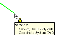
- Enter the vertex ID of the vertex in the model at which you want to begin the line in the ID: field. The vertex ID of a vertex can be determined by hovering the cursor over a point. A pop-up will appear with the vertex ID as shown below.
Add a New Part to a Model
New Part: Selecting this command adds an empty part with the next available part number. Any type of geometry can be added to this part.
Add Construction Nodes to a Model
Construction Vertex: Use this command to add a vertex (node) to the model. Construction vertices have two purposes:
- Used as a reference point to add hand-built geometry to the model, such as lines, arcs, meshes, and so on. This vertex will not be included when the model is analyzed (unless of course an element is connected to the vertex).
- When working with a CAD solid model, construction vertices will force the surface mesher to create a node at that location. Refer to the
Construction Vertices -Seed Points page for details.
- The Define Construction Vertex dialog will appear.
- Enter the coordinates where you want the construction vertex to be added.
- Press <Enter> to add the vertex.
 Visibility Construction Vertices to display or hide the construction vertices.
Add Lines to a Model
Line: Use this command to add a line segments to the model. This segments can be defined as any line element.
- The Define Geometry dialog will appear.
- First specify the part, surface and layer to which the lines will be assigned in the Attributes section. The lines can be placed in any surface or layer number.
- Specify the beginning coordinate for the line using one of the above methods in Common Items. If you move the mouse, you will see that the cursor is rubberbanded to the endpoint.
- Specify the second endpoint of the line. You will see the line appear in the viewing area.
- You can continue to add more lines in this dialog. You can either continue from the last endpoint, or can start a separate line. This can be controlled by the
Single Line
check box.
- To enter a series of line elements that are connected together to form a continuous chain, make sure that the Single Line check box is deactivated.
- To define separate lines that do not connect together, make sure that the Single Line check box is activated.
Modify Set Search Tolerance dialog. This rule has an effect when adding geometry, copying, meshing, and so on.
 Options Sketching tab.
Generate Tangent Lines
Selecting the Tangent Line command guides you through the process of creating tangent lines between construction circles and arcs. This command will only be available if an arc or circle exists in the current sketch. Following the prompts in the status bar, the tangent lines are created as follows:
- Click the first object for the tangent: either a construction vertex, circle, or arc.
- Click the second object for the tangent: either a construction circle or arc (or vertex if the first object was not a construction vertex). All possible tangent lines between the two objects will be shown.
- Select each possible tangent line that you want in the model. Use the <Ctrl>, <Shift> and <Ctrl>+<Shift> to toggle, add, and subtract lines to the selection set.
- Press the <Enter> key after selecting the desired lines. Construction lines will be created at the selected tangent lines.
Add Rectangles to a Model
Rectangle: Use this command to add four line segments that define a rectangle.
- The Add Rectangle dialog box appears.
- First specify the part, surface and layer to which the lines generated from the rectangle will be assigned in the Attributes section.
- If not in sketch mode, then four points will be required to define the rectangle. If in sketch mode, only the two diagonally opposite points are required. Each of these points can be entered as described above in Common Items. The four points are as follows:
- The first point defined must be a corner of the rectangle.
- The second point defined must be the corner of the rectangle opposite to the first point.
- The third point defined can be any point that lies in the plane of the rectangle. This point cannot lie along the diagonal defined by the first two points.
- The fourth point defined can be any point on the base of the rectangle.
- Press the Apply button to create the line segments.
- For example, to create a 10 x 10 rectangle at the origin in the XY plane at Z=0 and sides parallel to X and Y, you would use the following coordinates for the four points:
- (0,0,0) for the first corner
- (10,10,0) for the opposite corner
- (2,3,0) or any coordinate where the X and Y values are unequal (so that they are not on the diagonal) and Z=0.
- (1,0,0) or any coordinate along the X axis, except for (0,0,0).
Add Arcs to a Model
Arcs can be added in 3D space using
Arc Three Points
or
Arc Center and Endpoints. When in sketch mode, arcs can also be entered by specifying the
Angle and Endpoints or
Radius and Endpoints.
- The Define Arc using dialog will appear.
- First specify the part, surface and layer to which the arc (or lines) will be assigned in the Attributes section.
- If not creating a construction object, specify how many line segments into which the arc will be divided in the Minimum Segments: field. The segments will be of equal length. To control the lengths of the lines create from the arc, activate the Maximum Length: check box and specify the maximum length of the line segments that will be generated in the adjacent field. If the length of the arc divided by the value in the Minimum Segments: field is greater than this value, more segments will be generated than specified in the Minimum Segments: field.
- Define the points for the arc, following the prompts in the status bar. Each of these points can be entered as described above in Common Items.
- For some arc commands that have a direction, activate the Reverse Sense of Arc check box to have the other section of the arc displayed.
- Press the Apply button to create the arc or line segments.
Add Circles to a Model
Circle Diameter or
Circle Center and Radius: Use these commands to add circles to the model.
- The Define a Circle by Diameter Points or Define a Circle by Center and Radial Point dialog will appear.
- First specify the part, surface and layer to which the lines generated from the circle will be assigned in the Attributes section.
- If not creating a construction object, specify how many line segments into which the circle will be divided in the Minimum Segments: field. The segments will be of equal length. To control the lengths of the lines create from the circle, activate the Maximum Length: check box and specify the maximum length of the line segments that will be generated in the adjacent field. If the circumference of the circle divided by the value in the Minimum Segments: field is greater than this value, more segments will be generated than specified in the Minimum Segments: field.
- Define the points for the circle, following the prompts in the status bar. Each of these points can be entered as described above in Common Items.
- Press the Apply button to create the line segments.
Add Splines to a Model
Spline Curve: Use this command to add splines to the model.
- The Add Spline dialog will appear.
- First specify the part, surface and layer to which the lines generated from the spline will be assigned in the Attributes section.
- If not creating a construction object, specify how many line segments into which the spline will be divided in the Minimum Segments: field. The segments will be of equal length. To control the lengths of the lines create from the spline, activate the Maximum Length: check box and specify the maximum length of the line segments that will be generated in the adjacent field. If the length of the spline divided by the value in the Minimum Segments: field is greater than this value, more segments will be generated than specified in the Minimum Segments: field.
- Specify the degree of curvature that will be used to generate the spline in the Degree: field.
- If you want the spline to pass through all of the defined points, activate the Interpolate check box.
- If you want the first and last point to be connected, activate the Close check box.
- Define the points that will be used to generate the spline. Each of these points can be entered as described above in Common Items.
- Press the Apply button to create the spline or line segments.
Layer Control
The Layer Control command controls the display of lines according to the layer attribute (layer number). You can also use this command to filter layer, preventing entities from being selected while maintaining their visibility. The dialog box shows all of the layer numbers in the model, regardless of the part.
Click the Show checkbox (in the table heading) to enable or disable the visibility of all layers in the model. You can also hide or show individual layers using the provided checkboxes in the Show column.
Click the Filter checkbox (in the table heading) to enable or disable the selection of all layers in the model. You can also filter layers individually using the provided checkboxes in the Filter column. Ensure that the Show option is enabled for lines to remain visible while filtering them to prevent selection.
Contact Elements
See the separate Contact Elements page for help with using this command.
Centroid Creator
See the separate Centroid Creator page for help with using this command.
Add a Pulley Element
The Pulley command is available only for nonlinear analyses. See Pulley Elements for more details.