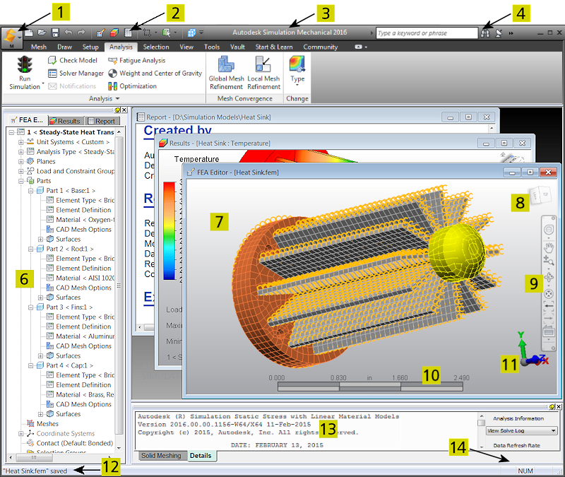
Key features of the user interface:
Legend:
- Application Button: Opens the Application Menu. Use this menu to access file open, close, and save commands; the recent files list; archive functions; program options; and more.
- Quick Access Toolbar (QAT): A customizable set of frequently accessed commands. Click here for more information.
- Title Bar: The Windows standard title bar displays the program name. If the display area is maximized, the title bar also shows the model name .
- Infocenter: Search the program help or access the Community Center, Autodesk Exchange Apps, and Help/About information using the commands in the InfoCenter toolbar.
- Ribbon: Located just below the title bar and contains the commands, organized into logical tabs and panels within tabs. Help for individual ribbon tabs can be accessed using the links at the bottom of this page.
- Browser (Tree View): Lists various program and analysis settings (such as the analysis type and units systems), loads and constraints, parts of the assembly, contact settings, and more. Each of the environments, indicated by the three tabs at the top of the browser, performs a different function and includes different browser contents. The browser can be dragged to the desired width. It can also be Unpinned so that it auto-hides when the cursor is not at the left side of the screen.
- Display Area: Where the modeling activity takes place. The title bar of this window displays the environment in use and the model name. Activating one of the tabs on the browser activates the corresponding display area and vice versa.
- ViewCube: Used to manipulate the model views. Click here for more information.
- Navigation Bar: A collection of tools for navigating and manipulating the model display. Click here for more information.
- Miniaxis: Shows your viewpoint within to the three dimensional working area (that is, the directions of the three global axes). The miniaxis location is customizable. Use the View
 Appearance User Interface Show Scale Ruler and
  Options Graphics commands to control the visibility, location, and size of this item.
 - Scale Ruler: Shows the relative size of the model in the current display units. Use View Appearance User Interface Show Miniaxis and Options Graphics commands to control the visibility and size of this item.
- Status Bar: Displays various command prompts and status messages.
- Output Bar: Provides access to the solid meshing results, solve log, analysis summary, and the convergence plot (for local mesh refinement and nonlinear analysis solutions). You can drag the Output Bar to the desired height. You can also Unpin the Output Bar so that it auto-hides when the cursor is not at the bottom of the screen.
- Additional Status Indicators: The items in this corner indicate when Caps Lock, Num Lock, and Scroll Lock keyboard options are active. An icon also indicates when a floating license has been borrowed.
Simulation Mechanical Program Environments
FEA Editor Environment
This environment is the primary modeling environment. Use it to create meshes; apply loads and constraints; define elements, material, and analysis parameters; and perform the analysis. Solid or midplane meshes can be generated for models created by various CAD solid modeling applications. The CAD models can be either a single part or an assembly. The files can be in the supported proprietary CAD formats or universal file formats. 2D sketches can be created and meshed to create 2D models. Structured meshes can also be drawn manually within this environment. You can access the FEA Editor environment using the following options:
- If you have a CAD application for which direct transfer technology exists, select the Autodesk Simulation Mesh (or similar command) in the CAD program. The command may be located on a ribbon or in a pull-down menu, depending upon the application. This action transfers the model into the FEA Editor environment of Simulation Mechanical.
- Select Open and choose the proper file type in the Files of Type drop-down box. The file types are organized under Autodesk Simulation FEA Files, CAD Files, or Non-Autodesk Simulation FEA Files headings. The model opens in the FEA Editor environment.
Results Environment
View the results of all analyses. This environment uses many output files created during the analysis and shows how the model reacts to the applied loads. The Results environment can be accessed by selecting Tools Environments Results in the FEA Editor. You can also click the Results tab at the top of the browser. The Results environment will open automatically after a currently running analysis is finished or after performing a Check Model operation. For certain analysis types, the model is displayed within the Results environment while the solution is progressing. For example, when running MES and transient heat transfer analyses, you can view partial results as the solution progresses.
Report Environment
Generates an HTML report for presentation of the results of the analysis. Images and animations created in the Results environment can be inserted into the report. You can also save the report in various document formats.
MultiLanguage Support
By default, the environments are designed to detect the language in use based on the Windows regional settings and adjust the graphical user interface. To switch to any of the different languages that are supported, use the following procedure:
- Create an environment variable named ALGOR_LOCALE_OVERRIDE. It can be either a user variable or system variable depending on whether it affects only the current user or all users of the computer. (Refer to your Windows documentation for instructions on setting environment variables.)
- Set the value of the variable to one of the following three-character strings:
Language Value of Environment Variable German DEU English ENU French FRA Italian ITA Japanese JPN Simplified Chinese CHS - Click OK to save the variable and start the software. All menus and labels display with the new language. Numerical input follows the locale override convention for the decimal point character. However, dialog boxes and windows provided by other vendors continue to display in the language set by the regional settings.
Ribbon Tabs and Ribbon Commands
Some ribbon tabs, and the commands they contain, are documented within the pages listed under Topics in this section at the bottom of this page. Tabs that are not listed are documented within the context of the appropriate simulation workflow topics. For example:
- Mesh and Draw commands are covered within the Meshing branch of the User's Guide.
- Model Setup commands are covered in the Set Up and Perform the Analysis branch of the User's Guide. The setup commands and procedures are organized in this branch according to the analysis type.
- For the Vault documentation, click here.
- For an overview of the resources available from the Start & Learn and Community tabs, watch the Keep Learning video in the New User Quick Start section.