When you select objects, you specify what type of object you want to select (lines, parts), and how you want to select it (point, rectangle). In addition, the <Shift> and <Ctrl> keys can be used to adjust the selection method (add, toggle, subtract).
Set type of object to select
You set the type of object to select under Selection Select. You can also find the same commands under Quick Access Toolbar Select.
Options available in all environments
- Click Selection Select Parts to select entire parts. You can also select parts in the browser (tree view).
- Click Selection Select Surfaces to select surface entities. You can also select surface entries in the browser. Tip: With one or more parts selected in the Results environment, you can right-click and control transparency of the parts. You can also right-click to control the visibility of the results, the mesh, or the faces of selected parts or of selected individual surfaces. When Visibility of Results is unchecked, the part color is used instead of the current result contour colors.
Options available in FEA Editor environment
- Click SelectionSelectEdges to select edges. You can apply an edge force, boundary condition, or elastic, rigid, or displacement boundary element to edges you select. Note: Edges only exist for models that originate in a CAD solid model application.
- Click Selection Select Lines to select lines. Use when you change the layer attributes for lines in your model.
- Click Selection Select Construction Objects to select construction circles, arcs, lines, and vertices.
- Click Selection Select Vertices to select vertices. Use to apply boundary conditions and forces to vertices. Note: If a vertex coincides with a snap point on a construction object, you can hide the construction object. You can also click near the vertex or use a rectangle selection.
Options available in Results environment
- Click Selection Select Nodes to select nodes. Use to view the results at a specific node.
- Click Selection Select Elements to select elements. Use to view element statistics.
- Click Selection Select Faces to select element faces. Use to view results on element faces such as the heat rate of a face.
- Click Selection Select Beam Members to select beam members for code checking.
- Click Selection Select Loads and Constraints to select FEA-type objects such as loads and boundary conditions. Use Results Inquire Inquire Loads and Constraints to list properties for selected FEA-type objects.
Set how to select objects
How you select objects is set from SelectionShape. You can also find the same commands under Quick Access Toolbar Select.
Combination selection mode—click a single object or use a rectangle to select multiple objects:
This mode will suit the vast majority of selection tasks. Click to select the object at the cursor location. Alternatively, hold down the left mouse button, drag to draw a selection rectangle, and release the button. In the FEA Editor, objects fully enclosed within the rectangle will be selected. In the Results environment, objects that the rectangle intersects will also be selected.
- Click Selection Shape Point or Rectangle.
- Click near the target object, or click and drag to draw a rectangle enclosing the target objects.
Use a rectangle to select multiple objects:
- Click Selection Shape Rectangle.
- Click in the display area to set the first corner of the rectangle.
- Click in the display area to set the diagonally opposed corner. Note: The Rectangle selection shape is useful when panning of the view is required between the first and second click (in other words, when the area being selected overflows the display area width). An example of this is when the amount of zoom needed to clearly isolate the objects being selected causes a target object to be at least partially off-screen.
Use a polygon to select multiple objects:
- Click Selection Shape Polyline.
- Click in the display area to begin the polygon.
- Click in the display area to set the polygon corners. Use the <Esc> key to return to the previous corner.
- To close the polygon...
- Click near the initial point. A small box with the word Close will appear at the cursor location, which indicates that the last segment will snap to the initial point when you click, closing the polygon.
- Press <Enter> to automatically close the polygon. A segment will be created from the last point clicked to the initial point.
Use a circle to select multiple objects:
- Click Selection Shape Circle.
- Click in the display area to set the circle center.
- Click in the display area to set the circle diameter.
Use Reset To Point:
When active, Reset To Point resets the selection shape to Point or Rectangle after you perform a selection. The command functions as a toggle—click it to activate the option and click again to deactivate it. The option highlights when active.
If you typically use the Point or Rectangle selection shape, you may find it convenient to use Reset To Point. For example, when Reset To Point is active and you perform a Polyline selection, the selection shape reverts to Point or Rectangle once you close the polygon. If you want to make multiple selections with other shapes, such as Polyline or Circle, deactivate Reset To Point.
Selection methods
You can use four methods when you select objects with the selection shapes:
- Default Method This method is active when you select objects with the mouse and no hot keys. Using this method, the objects in your current selection region are the only objects in the selection set. Previously selected objects outside of your selection region are unselected.
- Toggle Method This method is active when you hold down the <Ctrl> key and make multiple selections. Using this method, the selection status of the objects in your current selection region is toggled from the original status. The status of the objects outside of your current selection region are not changed.
- Add Method This method is active when you hold down the <Shift> key and make multiple selections. Using this method, the objects in your current selection region are added to the selection set. Any objects previously selected and outside the current selection region remain selected. If you select an object that is already selected, it remains selected.
- Subtract Method This method is active when you hold down both CTRL and SHIFT and make multiple selections. Using this method, the objects in your current selection region are subtracted from the selection set. Any objects previously selected and outside the current selection region remain selected. If you select an object already unselected, it remains unselected.
The following commands are similar to the selection methods but operate on the entire model:
- Click Selection Select None to unselect everything. You can also click the <Esc> key if the cursor is in a selection mode.
- Click Selection Select All or <Ctrl><A> to select all objects of the current selection type and unselect other types of objects.
- Click Selection Select Invert to unselect objects not in the current selection type and invert the items selected in the current selection type. For example, if part 1 and some other vertices were selected, the Invert command in part selection mode selects all parts except for part 1. While in vertices selection mode, the Invert command selects all vertices except the original ones.
Set the filter
Use the filter to control the items you select.
- Click Selection Filter Loads Constraints to filter the selection set for the appropriate FEA objects. In the Filter dialog, options are available based on the analysis type and selection method. The options you select in the filter determine which objects remain in the selection set.
- Click Selection Filter Line Length to select lines between the minimum and maximum filter lengths.
- Click Selection Filter All Parts/Surfaces or Selection Filter No Parts/Surfaces to change the filter status for all parts and surfaces. You can also right-click parts and surfaces in the tree view and select or clear Enable Filter. The filter icon
 appears on appropriate items when the filter is on.
Expand Your Selection
-
Select Neighbors:
When the Selection
Expand Select Neighbors option is active, and you click a vertex, line, or edge on the model, the immediately adjacent vertices, lines, or edges are also selected. For example, if you select a line in the middle of a square grid, all lines in contact with the line you click are also selected. Similarly, if you select a vertex, the vertices at the opposite ends of the lines connected to the vertex you click are also selected: 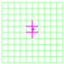 …
… 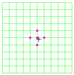
Figure 1: Select Neighbors Behavior for Lines (left image) and Vertices (right image)
Note: The Select Neighbors option is only available in the FEA Editor environment and only when the Select option is Vertices, Lines, or Edges. -
More Neighbors:
Use the Selection Expand More Neighbors command after you select one or more vertices or lines. This command adds all of the immediately adjacent vertices or lines to the current selection set. Use this command several times to quickly select vertices or lines in a specific area of a model. Note: The More Neighbors command is only available in the FEA Editor and only when one or more vertices, lines, or edges are currently selected.
-
All Neighbors:
When the Selection Expand All Neighbors command is clicked, the selection propagates in all directions from the initially selected surface. This propagation continues until a hidden surface or the end of the currently selected part is encountered. An example application for this tool is to quickly select all interior surfaces of a complex pump housing. You merely have to hide outside surfaces that intersect pump inlets and outlets. Note: The All Neighbors command is only available in the FEA Editor and only when one or more surfaces are currently selected.
-
Select Chain Border:
In line select mode, use Selection
Expand Chain Border to select a chain of lines beginning and ending with the line you select. The chain also ends when it runs into a previously selected line. This command is useful for selecting the perimeter of a part or hole. The Selection
Expand Chain Border Largest Chain setting determines which chain of lines you select. If the selection is not appropriate, try toggling the Largest Chain option. In general, to select the outside perimeter, use this option. To select an internal perimeter with sharp corners, do not use this option. Note: The Chain Border and Largest Chain options are only available when the Select option is Lines. The Largest Chain setting affects the outcome when the algorithm is choosing which line to next add to the selection. If Largest Chain is active, the algorithm attempts to choose the line that is most nearly collinear with the current line. If Largest Chain is not active, the algorithm chooses the line that makes the sharpest angle with the current line.
Select Related Objects (change the types of objects in selection sets)
You can right-click in the display area and click Select Related to change the type of objects selected. You can also click Selection Related type of entity in the ribbon. For example, if you select a part, but want to apply pressures to all the surfaces on the part, right-click and choose Select Related Surfaces. All surfaces on the part are selected.
The following table displays the geometry object hierarchy for the FEA Editor and Results environments. Objects above a given entity type are parents, and objects below a given entity type are children. The available object types vary depending upon which environment you are using. You can change the selection set objects to any parent or child entities related to the select entities. For example, if your selection set consists of Surfaces, you can select the related Lines or Vertices within the originally selected surfaces, or you can select the related Parts to which the originally selected surfaces belong.
|
Table 1: Object Hierarchy
Select setting to the chosen parent or child entity type.