Accessing the
Mesh Matching options:
Mesh Mesh 3D Mesh Settings Options. Then, click the
Mesh Matching icon. The
Mesh Matching icon is present regardless of which radio button is selected in the
Mesh type section of the
Model Mesh Settings dialog. This icon also appears both for single-part models and assemblies. The reason is that mesh matching can be performed within single parts where they self intersect, not just where adjacent parts of an assembly meet.
Mesh 3D Mesh Settings Options. Then, click the
Mesh Matching icon. The
Mesh Matching icon is present regardless of which radio button is selected in the
Mesh type section of the
Model Mesh Settings dialog. This icon also appears both for single-part models and assemblies. The reason is that mesh matching can be performed within single parts where they self intersect, not just where adjacent parts of an assembly meet.
The options that appear within the Mesh Matching tab depend on the following three items:
- The state of the
Use VCAD option (Mesh Mesh Use VCAD): Virtual imprinting options are only available when this option is activated.
- Whether the model is a single part or an assembly (multi-part): Mesh matching options and virtual imprinting between parts is only applicable to assemblies. These settings do not appear for single-part models.
- The analysis type.
Mesh Use VCAD is activated, the virtual CAD mesh engine is used. When not activated, the pre-Version-21 meshing routine is used. Because of the benefits of the virtual CAD mesh engine over the legacy mesh engine, only use the legacy mesh engine if you encounter a problem with the virtual CAD mesh engine on a particular model.
Each control described on this page is identified as working with the VCAD mesher, the legacy mesher, or both.
Mesh Matching Settings
Create matched mesh between parts: (Available only for assemblies when using the VCAD mesh engine.) This option is activated by default. A matched mesh is the easiest and most direct way to bond adjacent parts. Matching meshes are also required for surface contact in linear analyses solved using the native SimMech processor. However, there are some situations where generating an unmatched (non-conformal) mesh may be advantageous. For example:
- For MES or nonlinear static analyses with general surface-to-surface contact, the best performance and results are obtained when the meshes do not match between parts (non-conformal mesh). In nonlinear solutions contact is detected between a node on one part and an element face on the adjacent part. When the nodes are matched, the contact solution can oscillate between the element faces around each node, making convergence difficult.
- For large or complex assemblies, or assemblies in which the part size varies drastically, successfully matching the meshes of all of the parts can be problematic. The mesh can fail for some parts, or the surface mesh may be distorted near part intersections.
- In addition to this location, you can also find the
Create matched mesh between parts option in the dialog that appears when you firs click
Mesh Mesh 3D Mesh Settings. You can activate of deactivate the option from either location; the options are linked and remain in sync.
- When you deactivate the Create matched mesh between parts option, virtual imprinting is also disabled. However, you can reactivate virtual imprinting without reactivating the Create matched mesh between parts option.
- For linear analyses solved using the native SimMech processor, parts with unmatched meshes can be bonded by enabling one of the Smart Bonding options (found within the General Contact Settings dialog. Neither smart bonding nor matched meshes are required for bonded contact when using the Autodesk Nastran solver. In addition, the Nastran solver does not require matched meshes for linear surface contact. Finally, the Nastran solver can also bond parts that are separated by a gap (using the Offset Weld type of contact).
Do not match the mesh of surface contact pairs: (Available only for nonlinear analyses of assemblies when using the VCAD mesh engine.) Use this option to prevent forcing the meshes to match between two touching surfaces when they are defined as an explicit Surface contact pair. The nonlinear contact solution is more stable, and the analysis runs faster, when the meshes are not matched along contacting surfaces. The exception to this rule is Point to Point contact (see the last bullet of the following note).
- Even when you choose to not match the meshes, the meshes on adjacent surfaces may still be the same size (and therefore matched) if the following conditions exist:
- Edges of the two contacting surfaces are coincident,
- The specified mesh size for the two contacting parts is the same, and
- The surface areas are identical.
For this reason, disabling virtual imprinting may be advantageous when trying to produce an unmatched mesh. However, virtual imprinting is a global setting, and disabling it may therefore have an undesirable affect on bonded contact pairs (where you do want the meshes matched). In such cases, you could use Tied surface contact between bonded parts or surfaces.
- For the Do not match the mesh of surface contact pairs option to work, define the applicable contact pairs before meshing the model. If the applicable contact type is defined after the model is meshed, the model should be remeshed to prevent forced mesh matching along the contact surfaces.
- There are some points where the mesh has to align. Imagine two cubes of the same size in contact, with the edges of the mating surfaces coincident. Since the four corners are at the same location, these nodes will match. The rest of the mesh will not be forced to match. Although the four corners match, separate nodes are created at each corner when the model is analyzed (one for each part).
- Disable the Do not match the mesh of surface contact pairs option if using the Point to Point contact type. Point to Point contact requires the meshes to match (unlike the other contact types, which are based on contact between a node on one part and an element face on the adjacent part).
Mesh matching tolerance section:
CAD models are not perfect. Even if the parts are drawn in perfect contact, the internal representation of the surfaces may result in adjacent surfaces that are not coincident. In other situations, parts are drawn in their as-machined or stress-free condition, even though the interaction of assembled parts may cause the dimensions to change. For example, the parts in a press-fit assembly are drawn with an interference. Mesh matching tolerances are used to compensate for such discrepancies. Any two nodes that are within the mesh matching tolerance will be snapped together.
On-surface tolerance based on: (Available when using either mesh engine, for assemblies only.)
- Fraction of surface mesh size: If this option is selected, the surface mesh process will search for nodes within the radius defined by the average length of the elements (in the surrounding area) multiplied by the value in the Tolerance value field. Nodes within this radius will be snapped together. Thus, this option results in a different matching tolerance at each region of the model if the mesh size varies.
- Absolute length dimension: If this option is selected, the surface mesh process will search for nodes within the radius specified in the Tolerance value field of each node to match the meshes of coincident surfaces.
- Fraction of automatic mesh size: This option is similar to Fraction of mesh size in that the nodes are snapped if they are within a distance of the mesh size multiplied by the value in the Tolerance value field. The difference is that the mesh size is not based on the size of the elements at the area in question. Instead, the mesh size is based on the size of mesh that would result if meshed at 100% mesh size. Thus, setting a different mesh size and using refinement does not affect the tolerance dimension. However, the 100% mesh size is affected by which parts are selected for meshing.
Tolerance value: The value in this field will determine how far the surface mesh process searches for node on coincident surfaces to match the meshes. The meaning of this value, whether it is a dimension with units of length or a multiplier, depends on the option selected in the On-surface tolerance based on drop-down box.
Virtual imprinting section
When one of the Use virtual imprinting options is activated, the software detects where feature lines of one surface lie on the surface of an adjacent part or surface. It does not create an intersection if the two surfaces are passing through each other (such as an interference).
Between parts:
(This option is available only when using the VCAD mesh engine.)
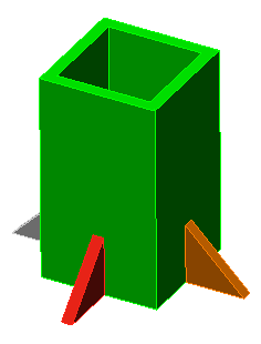
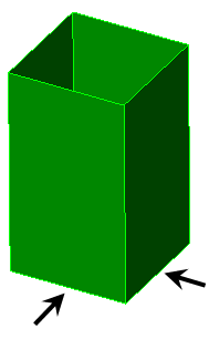
When activated, the faces of different CAD parts are split in memory where they intersect each other, without creating additional surface numbers (that is, a virtual imprinting of one surface on another without generating a new subsurface in the model). The virtual model is used as the basis of surface mesh generation. Since the matching virtual surfaces are meshed only once, this option results in a better quality mesh. When unchecked, mesh matching is accomplished by meshing both surfaces of the parts and adjusting the mesh on one part to conform to the mesh on the other part. See Figure 1.
|
(a) Example solid model consisting of an assembly of multiple parts.
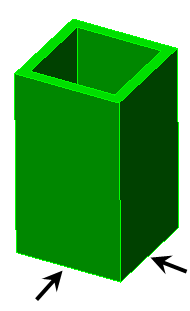
(b) Use virtual imprinting not activated. Virtual surfaces are not created at the arrows.
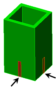
(c) Use virtual imprinting activated. The surface of the pole is split where the gussets make contact (arrowed), making a new surface in the virtual copy of the model. (New surfaces are not created in the actual model.) |
|
Figure 1: Use virtual imprinting in a Solid Model |
Within a part:
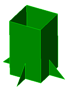
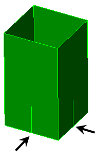
This option creates virtual intersections where different surfaces within a single part meet each other. The action is similar to that of imprinting between parts. This feature is useful for CAD surface models used as a basis of plate/shell FEA models. Such models frequently use single parts comprised of several different surfaces each but without feature lines present along surfaces where an intersection with an adjacent surface occurs.
|
(a) Example plate model consisting of one part. |
|
(b) Perform imprinting within parts not activated. The virtual feature line is not created at the arrows. The mesh of the gusset may not match the mesh of the pole. |
|
(c) Perform imprinting within parts activated. The surface of the pole is split where the gussets make contact (arrowed), making a new feature line in the virtual copy of the model. The meshes will match. (New feature lines are not created in the actual model.) |
| Figure 2: Use virtual imprinting in a Plate/Shell Model |
Imprint tolerance:
The tolerance for virtual imprinting is specified separately from the mesh matching tolerance. The tolerance in the Virtual imprinting section is used to specify the maximum distance between surfaces and adjacent features, within which distance an intersection will be created. Increase the tolerance if valid intersections are being missed. Decrease the tolerance if unwanted intersections are being created between objects that are close but do not actually meet.
- Surface splitting of a model is similar to imprinting but is a separate function. Surface splitting creates additional surfaces and feature lines in the FEA model. Surface splitting only works on a part-to-part basis (wherever surface areas are in common), whereas imprinting works on a part-to-part basis and also within a single part. Imprinting can also create area, line, and point intersections. See the Surface Splitting page for details on surface splitting.
- The Imprint tolerance affects both part-to-part imprinting and imprinting within parts.