This page concerns the advanced parameters for general surface-to-surface contact in nonlinear simulations run using the native Simulation Mechanical (SimMech) solver. These parameters are located in the Advanced tab of the Contact Options dialog.
Parameters Section
The first two options (radio buttons) in the Parameters section specify the general type of contact that may occur at any time in the analysis. This selection controls the behavior of the automatic contact stiffness calculation. In some cases, the choice is obvious. In other cases, it may not be clear whether the situation represents low speed or high speed contact. The difference is a matter of solving efficiency. Either selection should give accurate results. The options available are as follows:
Low-speed contact (press-fit): The contact between the pair is characterized as bringing the parts together slowly (low speed), or the parts are in continuous contact (press fit). The adaptive contact stiffness routine can be used, but is not the default.
High-speed contact (impact): The contact between the pair is characterized as a rapid change occurrence, such as an impact or drop test. Again, the adaptive contact stiffness routine is not used by default, but it might be helpful in some cases.
Contact type: It is somewhat misleading to describe contact as surface-to-surface. What happens in reality is that the nodes on one part/surface contact the element faces on the other part/surface, thereby preventing surface penetration (the exception being the point to point contact option). This node-to-face contact can be unidirectional (secondary nodes contacting primary faces only) or can be bidirectional (primary nodes also contacting secondary faces). Choose one of the following four options:
- Automatic: (This is the default option.) The processor selects between Point to Surface and Surface to Surface contact based on the mesh along the contact surfaces and the material models involved. The processor also determines which surface acts as the primary surface. (The processor may switch the first and second part/surface before the analysis begins.) However, the Automatic option may not pick the best contact type when large deformation occurs in the analysis. In this case, check the validity of the setup chosen by the solver. The type of contact selected is listed in the log file (with the element count in each part). If the solver switches the first and second part/surface, that too is listed in the log file.
- Surface to surface: This option indicates that contact occurs when the nodes on the secondary part try to pass through the surface of the primary part and also when the nodes on the primary part try to pass through the surface of the secondary part. This type of contact is analogous to General (symmetric) contact using the Nastran solver.
- Point to surface: This option indicates that contact occurs only when nodes on the secondary part try to pass through the surface of the primary part. The nodes on the primary part/surface are free to pass through the secondary surface. This type of contact is analogous to General (unsymmetric) contact using the Nastran solver.
- Point to point: This method is best suited for situations in which the two surfaces have matched meshes and experience negligible sliding relative to each other. This option indicates that the contact occurs when the nodes on the secondary part try to pass through the nodes on the primary part; contact between the node and surface of the primary part is not detected. Regardless of how the parts move, the contact force is always between the original pair of nodes connected together. When
Point to Point
contact is created, the Results environment shows extra parts in the model—one
Contact
element part for each
Point to Point
contact pair.
Tip: Point to Point contact creates the same element type that you can create manually by drawing lines between nodes and assigning the Contact element type. The difference is that contact elements created by the Point to Point option can be zero-length initially, and contact can be initiated when their length is 0. Manually created Contact elements cannot be drawn zero-length and cannot initiate contact at a length of 0.
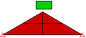
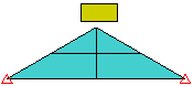
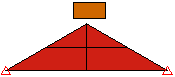
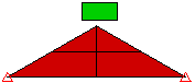
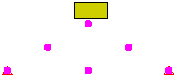
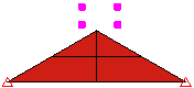
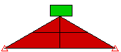
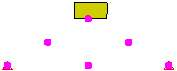
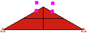
The point to surface method is faster than the surface to surface method. However, be aware that points on the first part could pass through surfaces on the second part when using point to surface contact. Surface-to-surface contact provides better contact detection, but at the expense of generating more contact elements. See Figure 1 for the comparative behavior of the different contact types.
| Surface-to-Surface Contact |
Point-to-Surface Contact (Block is Primary Part, Wedge is Secondary Part) (Points on the wedge contact faces of the block) |
Point-to-Surface Contact (Wedge is Primary Part, Block is Secondary Part) (Points on the block contact faces of the wedge) |
|---|---|---|
|
|
|
| Time = 0: | ||
Equivalent System. The surfaces of both parts are connected through contact. |
Equivalent System. Only the nodes on the wedge exist as far as contact is concerned. |
Equivalent System. Only the nodes on the block exist as far as contact is concerned. |
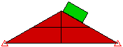
| Time = 0.024 seconds: | ||
The surface of the block contacts the surface/node of the wedge. |
The surface of the block contacts the node of the wedge. |
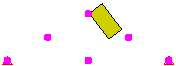
Contact does not occur until the nodes of the block contact the surface of the wedge. The wedge passes through the block. |
| Time = 0.12 seconds: | ||
The surface of the block slides down the surface of the wedge. |
The block passes in between the nodes of the wedge. |
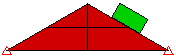
The block is stuck on the wedge. |
| Time = 0.15 seconds: | ||
|

|
|
|
Figure 1: Comparison of Contact Types Three models of dropping a block onto a wedge. Each model uses a different type of contact. |
||
Contact stiffness Section
By default, the contact stiffness is calculated automatically by the solver using the following equation:

where
- fs is the scaling parameter, and the default value is 0.1.
- E is the smaller of the Young's moduli of the two materials in the contact pair.
- A is the product of the contact line length and the thickness (2D) or the contact surface area (3D).
- V is the product of the area of the element and the thickness (2D) or the volume of the element (3D).
The ratio, A2/V, is calculated for elements of both the primary and secondary surfaces. The ratio values are averaged for surface-to-surface contact types. For other contact types, the ratio value for the primary surface is used. A value of 1.0 is used for this ratio for contacts that involve beam or truss elements.
User-defined: Activate this option to override the automatic contact stiffness.
Stiffness: This input field becomes available when the User-defined option has been activated. Enter an appropriate value in the field in units of force over length.
Additional stiffness: The optional stiffness you define in this field is added to the Stiffness value if surface penetration occurs. See Figure 2.
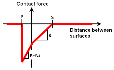
Figure 2: Contact Stiffness and Contact Distance
Two surfaces come into contact when the distance between the surfaces is less than the Contact Distance (S). Closer than this distance, the contact force at each element is proportional to the amount of compression (S – distance) and the Contact Stiffness (K). When the distance decreases to 0, the parts begin to pass through each other (penetration). The contact force is then proportional to the contact stiffness plus the Additional contact stiffness (Ka) and the amount of penetration. When the distance between the surfaces reaches the Maximum Penetration Distance (P), the contact force goes to zero, and penetration is no longer resisted.
The value for the contact stiffness should typically range from 1 to 10% (for "Unit" mesh size) of the Young's modulus value of the softer of the two materials in contact. For a mesh size that is too large or too small, you might need small increases or reductions in the percentage, respectively. If the assumed stiffness is too low, excessive contact penetration will occur. If the stiffness is too high, contact oscillation and instability is likely.
Another way to estimate the contact stiffness is to view the contact elements as a group of springs between the nodes of the two surfaces. If the contact force is known - even approximately - then the contact stiffness can be calculated from K = (F/n)/Δ, where F is the contact force, n is the number of nodes in contact, and Δ is the amount of compression in the contact elements to resist the force F/n. Keep in mind that the contact elements need to compress some amount to generate a force, so choosing a Δ of 10% of the contact distance (S) is a good starting point. However, this method could prove practical only for simple contact models with regular geometry.
Use adaptive contact stiffness method after first step: If you activate this check box, the contact stiffness is automatically adjusted throughout the analysis to provide improved accuracy and convergence. The contact stiffness is adjusted based on the status of the contact interaction (penetration, no penetration, oscillation). This method can provide more accurate and efficient solutions for some cases. For models involving contact between parts that are moving quickly moving relative to each other, or parts that have nonlinear material models, you may need to deactivate this option.
If the stiffness is too small, large penetration of nodes into the master surface is inevitable. If the stiffness is too large, the geometric boundary condition over the contact area is exactly fulfilled, but quite often the equilibrium iteration becomes unstable. High values of contact stiffness lead to ill-conditioning of the global stiffness matrix and result in poor convergence.
Contact distance Section
By default, the processor calculates a contact distance from the geometry of the model. The contact distance is the distance between the surfaces at which contact will occur. (See Figure 2.) If two surfaces are closer than this distance, the Contact stiffness is applied.
User-defined: Activate this option to override the automatic contact distance.
Contact distance Enter an appropriate value in this field. For example, if contact is occurring between a brick and shell part, set the contact distance to half of the shell element thickness (since the mesh is at the middle of the total thickness that the shell elements represent).
If the contact distance is larger than the initial gap between the surfaces, then an interference is created (Surface to Surface and Point to Surface contact only). A contact force occurs at the beginning of the analysis, which tries to separate the bodies. In this situation, it is typical to see the time step being reduced at the beginning of the analysis until the parts come into their new equilibrium.
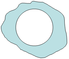
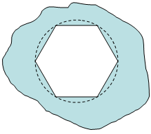
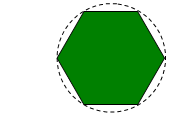
Special considerations are needed for closely spaced, moving parts - such as a shaft or pin inside of a hole. Mathematically, the gap between the parts may be smaller than the physical gap. The mathematical gap is determined by the size of the mesh and the approximation of the surfaces. The physical gap is based on the dimensions of the parts. As the approximated surfaces move or rotate, it is possible to create an interference that would not exist in reality. (See Figure 3.)
|
1. A hole in a part |
becomes a polygon when meshed. |
|
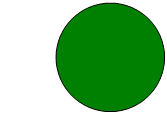
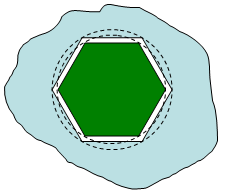
2. A round pin |
becomes a polygon when meshed. |
|
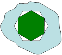
3. Combined, the two parts may fit without interference in some positions |
but interfere in other positions (even if the physical parts have a clearance). This is due to the approximation of the surfaces. |
| Figure 3: Clearances and Interferences Change When a Part is Meshed | |
To provide the same clearance (or interference) as the physical parts between two meshed parts, and to obtain the correct contact behavior, you may need to adjust the dimensions of the parts and the contact distance. These dimensions are related to the mesh size as shown in Figure 4.
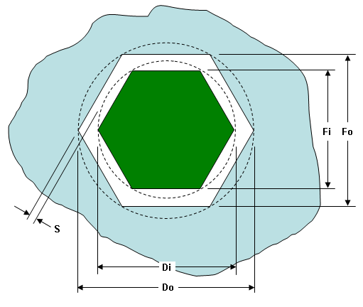
Figure 4: Relationship of a Pin and Hole to Avoid Interference
From basic geometry, you can relate the diameter D to the dimension across the flat F as:
![]()
To avoid an interference fit, set the dimensions based on the following guidelines:
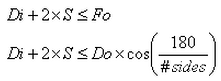
where:
- D, Di, and Do are the physical dimensions (real or theoretical dimensions)
- F, Fi, and Fo are the dimensions across the flats (due to the approximation by the mesh)
- # sides is the number of sides or elements around the perimeter. If the mesh around the perimeter is uniform, then this value is obvious. If the mesh is nonuniform, such as when using mesh refinement points, then the # sides is a hypothetical value based on how many sides (or elements) would exist if the coarsest mesh were used around the entire perimeter. Alternatively, you can measure the largest dimension Fo in the mesh.
- S is the mathematical clearance between the corners of the pin and the flats of the hole. If the surface to surface contact distance is set equal to this dimension, then there will be a 0 clearance gap at some positions of the pin and hole.
For example, take a 2-inch diameter pin inside a 2.010 inch diameter hole, and mesh each with 40 elements. The mathematical clearance S = 0.0019 inch; much less than the theoretical 0.005 inch clearance on each side. To have the 0.005 inch clearance with a contact distance of 0.002 inch, S = 0.007 inch, and the inner diameter must be 1.9898 inches.