This page concerns the geometry parameters for general surface-to-surface contact in nonlinear simulations run using the native Simulation Mechanical (SimMech) solver. These parameters are located in the Geometry tab of the Contact Options dialog.
Geometric parameters Section
Contact interaction distance: You can use this parameter to speed up the calculations. Contact is only considered if the two surfaces are closer than the value you specify. Thus, if the processor knows the two parts are far apart, avoids the steps of checking whether the parts are in contact. You need to be careful that the parts do not move too far from one step to another. Parts may not be in contact at either calculation step, even though the parts actually passed through each other from one step to the next. In this condition, no contact is detected. See Figure 1. For a value of 0 (the default), the contact distance is equal to the maximum dimension of a surface element on the parts. This assumption works in many cases but is possibly not suitable for high speed applications.

Figure 1: Contact Interaction Distance
A rapidly moving sphere is shown at four time steps (T=0,1,2, and 3). Contact is checked only when the bodies are within the contact interaction distance (dimension CID) of each other. In this example, the sphere is outside the contact interaction distance on all time steps, so the fact that it passed through the block is not detected.
Maximum penetration distance: Surface contact is not enforced when a node on the secondary part is more than the specified distance beneath the primary part surface. (The contact force goes to zero.) This entry is used to prevent enforcing fictitious contact between points on the secondary surface that are beneath the primary surface. If this entry has a value of 0.0, then the processor uses the maximum dimension of a surface element as its local maximum penetration distance. We suggest that the user should rarely use any other value beside 0.0 for this entry. If excessive penetration occurs while contact has been successfully detected, it is better to increase the contact stiffness rather than the maximum penetration distance.
Maximum initial distance: If the parts move significantly relative to each other, the automatic contact updating (on the Surface to Surface Contact main dialog box) is the best option to let the processor determine which points are actually in contact on each time-step. But in cases where the parts have little motion relative to each other, a faster analysis can be obtained if the user can minimize the number of contact elements that get generated. Contact is not created between elements which are initially farther apart than the Maximum initial distance. Therefore, contact will never occur between the elements, regardless of how close they move together. This will limit the number of contacts that are checked and thus speed up the analysis.
Imagine a pin inside a yoke and clevis. If the pin does not rotate relative to the yoke, then the left side of the pin will not make contact with the right side of the hole. Thus, setting the maximum initial distance to a small distance -- such as the size of one element -- will create just enough contact elements to connect the pin to the hole at adjacent nodes. The result will be a smaller model and less checking of the contact element status, so the analysis will run faster.
- The Contact Element Updating option (in the General Contact Settings dialog) is set to Never, or
- The Contact Type option (in the Advanced tab of the Contact Options dialog) is set to Point to Point.
This field is disabled for other settings.
If the value is 0.0 when Contact Element Updating is set to Never, Simulation Mechanical applies an automatic value, equal to two times the mesh size. (The automatic value is not applicable to Point to Point contact). The automatic value, or too small of a user-defined value, could result in contact interaction being missed. To avoid the possibility of missed contact, a value other than 0.0 is recommended.
Extend contact element sides: Surface to surface contact interaction regions can be thought of as an extension of the element's surface (extending outward in a direction normal to the face of the element). When a surface is convex, this extended contact interaction regions leaves gaps between two adjacent elements. The nodes on the adjacent part can penetrate through these gaps without contact being detected, or they can get stuck between the two elements. The result can be contact chatter as the node alternates between contacting the two adjacent elements. (See Figure 2a.) Choose from among the following three options:
- Automatic: If this option is selected, the contact element boundaries are extended automatically by a small amount to account for such gaps. (See Figure 2b.) If the
Automatic
option is selected, the processor detects when it is necessary to extend the contact surface length, and how far to extend it.
Target contact node
Two contact regions
(highly exaggerated)
Two contact areas extended.
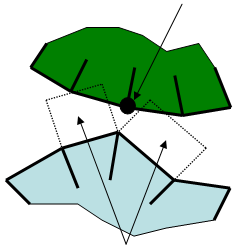
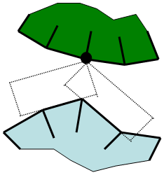
(a) Without extending the contact elements, the contact from one element to the next is not smooth as the target node slides across the surface. (b) Extending the contact elements gives a smoother contact area as the target node slides from one contact element to the next. Figure 2: Extend Contact Sides - Avoid: Use this option to prevent contact surfaces from being extended.
- Smoothed: Two issues originate from the non-smoothness of the contact surface, where smoothness is an indication of how much the normal direction changes between two adjacent elements. The first issue is poor convergence and the second is poor results. If two adjacent elements are not co-planar, such as on a curved surface, the normal vector of the contact force experiences a sudden change in direction when a target node travels across the element boundary. Such situations are inevitable as long as discrete geometry is being considered. This non-smoothness can cause oscillation across the element boundary and the target node can become stuck in the element boundary.
To minimize this situation, choose the Smoothed option from the Extend contact element sides drop-down menu. Selecting this option activates the Smoothing factor input field.
- Smoothing factor: Think of the smoothing factor as placing a fillet at the corner of two elements (or two sides of the same element). (See Figure 3 for clarification.) The smoothing factor is a value between 0 (no smoothing) and 0.5 (the transition region extends to half of the element's edge).
Note that smoothing does not occur at the junction between two different contact surfaces. It only occurs within the confines of each contact surface.
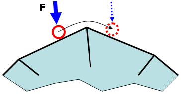
(a) A target node (red circle) on another body (not shown) is being forced into contact by the force F while moving from left to right. As the node moves from one element to the next, the direction of the reaction force changes instantaneously, which can lead to convergence difficulty.
smooth transition
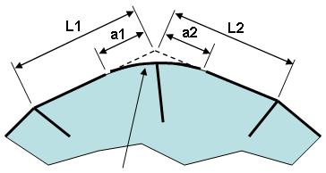
(b) By activating the Smooth by option, the sharp corner is eliminated. Thus, the direction of the reaction force changes smoothly as the node (removed for clarity) moves from left to right. The distances a1 and a2 are calculated as follows:
a1=smoothing factor * L1
a2=smoothing factor * L2
Figure 3: Smoothing the Contact Surface
Keep in mind that surface-to-surface contact is always checking whether the nodes on one surface are passing through the element faces on another surface. Thus, a node on surface A will contact the smoothed surface B, and a node on surface B will contact the smoothed surface A. Technically, the smoothed surface A does not contact the smoothed surface B.
Contact element updating parameters Section
Search radius: Specify the radius within which contact elements will be created each time they are updated. This field is only available if the User-defined contact element update frequency option is selected in the Contact Element Updating tab of the General Contact Settings dialog. Though the user-defined contact element update frequency is a global parameter, you must define the search radius separately for each individual contact pair.