With the Ports tab on the Feature Info palette, the port assignment of a duct on structures and in segments can be edited in 3D view. All the available ports are listed in the combo box. When you hovers the mouse over a port, the port will be highlighted; if the mouse stays for 1 second, the duct will show a transient preview for the geometry change. If port assignment is changed, the 3D geometry of the duct will be updated.
- Digitize a UG Primary Line with Duct.
- Insert a Vault with Transformer to connect with the line.
- Display either the Quick Info or the Feature Info palette.
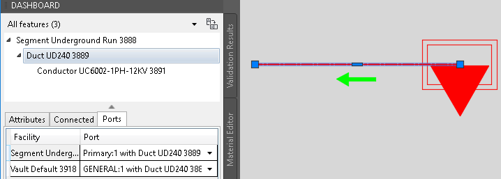
- Select the Duct and switch to the Ports tab.
You will see the feature shown after the current occupied port.
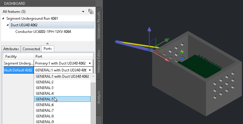
- Click the drop-down list to see all ports of the facility. If you hover the mouse over one port for more than 1 second, you can see the preview of the geometry change in 3D view.
The green circle indicates the port, and the yellow line is the preview of line 3D geometry.
- Click the port you want to assign to. The 3D geometry of the line will update accordingly.
If you select a port that was occupied by another line, the two lines are switched.
Note: The port assignment is controlled by the Port Connecting handler. If the Port Connecting handler is enabled, and if you assign an improper port, the system will revert it to the previous proper port automatically. If the handler is disabled, you can assign the port to any other ones.