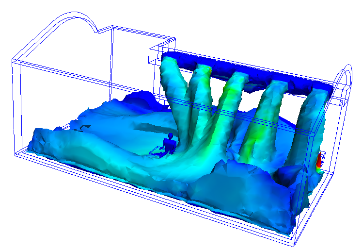
An iso surface is a surface of constant value. This is an example of a velocity magnitude iso surface colored by static pressure. The iso-surface shape indicates everywhere in the model that has a specific velocity magnitude. The colors indicate the static pressure at these locations.
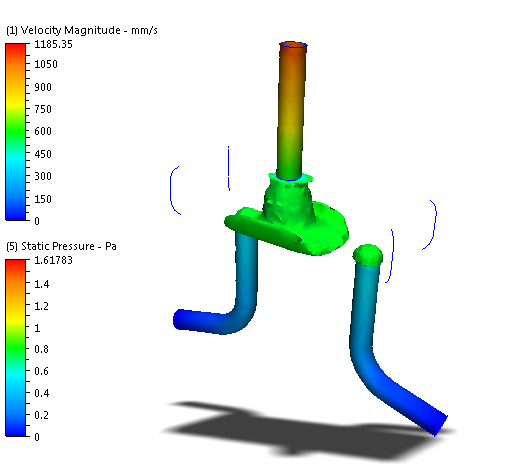
Iso surfaces are a three dimensional visualization tool that show a value as well as the physical shape of the flow characteristics. They are useful for visualizing velocity distributions in complicated flow paths as well as temperature distributions in thermal simulations. You can also use iso surfaces to determine the locations of the maximum and minimum values of a quantity.
Using Iso Surfaces
There are multiple ways to perform most Iso Surface tasks:
- On-model: Click directly on the model or the iso surface (as indicated). This is useful for maintaining focus on the model.
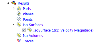
- Off-model: Use the Iso Surfaces branch of the Design Study bar or the Iso Surfaces context panel. This is useful for complex models in which it is easier to work away from geometry.
To Create an Iso Surface
- On-model: Right click on or near the model (not on an existing Iso Surface). Click Add Iso Surface.
- Off-model: Click Add on the Iso Surface context panel.
To rename an Iso Surface
- Right click on the desired Iso Volume in the Design Study bar, and click Rename.
To select an Iso Surface
- On-model: Left click directly on the iso surface.
- Off-model: Click its name in the Design Study bar.
To Hide an Iso Surface
- Uncheck the box adjacent to the Iso Surface in the Design Study bar. You can also right click on the name, and click Hide iso surface.
To Delete an Iso Surface
- On-Surface: Right click. Click Remove.
- Off-model: Right click on the desired Iso Surface in the Design Study bar, and click Remove
To Change the Appearance of an Iso Surface
- On-Surface: Right click. Select an option.
- Off-model: Click Edit from the Iso Surface context panel, and select from the Appearance menu.
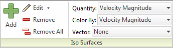
To change the Iso quantity and the Color by Result quantity
- On-Surface: Right click. Click Iso Quantity or Color by Result, and select from the list.
- Off-model: Select from the Quantity and Color by menus, respectively, on the Iso Surfaces context panel.
To change the value of the Iso quantity
- Drag the slider bar on the Controls dialog.
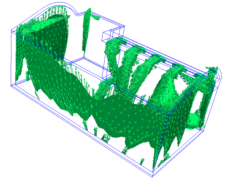
Vector Settings Controls
To enable vectors or to change the vector quantity
- On-model: Right click on the iso surface. Click Vector, and select the quantity.
- Off-model: Select from the Vector menu on the Iso Surfaces context panel.
To Change Vector Appearance
- On-model: Right click on the iso surface. Click Vector > Settings...
- Off-model: Click the arrow adjacent to Edit on the Iso Surfaces context panel, and select Vector Settings.
Click More... to make the following changes:
To control the display of arrowheads
- To disable arrowheads, uncheck Show arrowheads.
- To change the size of vector arrows, specify a value for the Arrowhead size. (The default size of 1 scales the arrowhead size based on the vector length.)
- To scale all vectors by the same amount, modify the value of the Scale factor.
To show regions where the active vector is within a specified range:
- Check Filtering.
- Enter a range in the Min and Max fields.
Click Reset or uncheck Filtering to display the entire model.