Vector_Map テクスチャ マップと MAXScript
はじめに
3ds Max 2014 以降で使用可能な Vector_Map テクスチャ マップ は、World Wide Web Consortium によって開発された標準の SVG XML オープン スタンダードを含むスケーラブル ベクター グラフィックス
ファイル形式をサポートします。また、.SVGZ フォーマットの圧縮 SVG、Adobe Illustrator の .AI ファイル、Adobe Portable
Document Format (.PDF)ファイルおよび Autodesk AutoCAD Pattern (.PAT)ファイルをサポートします。
ここで文書化された MAXScript への Vector_Map テクスチャ マップ オブジェクトの公開に加え、3ds Max 実装は、実際の SVG XML ファイル内の MAXScript 関数および式の専用サポートを提供し、ベクター グラフィックスを実際のシーン コンテンツとより密に結合することができます。これには、シーンのアニメーションに反応する、またはシーン
オブジェクトのプロパティに依存するダイナミック ベクトル グラフィックスの作成や、テキスト レンダリングを含む多くの機能が含まれます。
このトピックでは MAXScript を使用した SVG ファイルの作成、SVG XML ソース ファイル内部への MAXScript コマンドの包含について説明し、この機能のパワーを示すいくつかの例を提供します。
SVG ファイルの作成
基本的なフォーマット構造
SVG ファイルは XML 形式のテキスト ファイルです。そのコンテンツは <svg> タグで囲まれ、コンテンツを Scalable Vector Graphics
定義として識別します。
SVG ファイルの本文には、長方形、円、楕円、ライン、ポリライン、ポリゴン、イメージおよびテキストなど、1 つまたは複数のエンティティを定義することができます。
外側カラー(ストローク カラー)と内側カラー(塗り潰しカラー)は、16 進数値として定義することができます。ソリッド カラーの代わりにパターンとグラデーションを使用することもできます。
各エンティティに固有の各種のプロパティを定義することができます。そうでなければ、エンティティの値は既定値であるとみなされます。
エンティティを変換し、利用しやすいようにグループ化することができます。
| 最も単純な例:
|
<svg  xmlns="http://www.w3.org/2000/svg"
      xmlns:xlink="http://www.w3.org/1999/xlink">
    <rect x="255" y="255" height="512" width="512"
          style="stroke:#ff8800; fill: #0000aa"/>
</svg> |
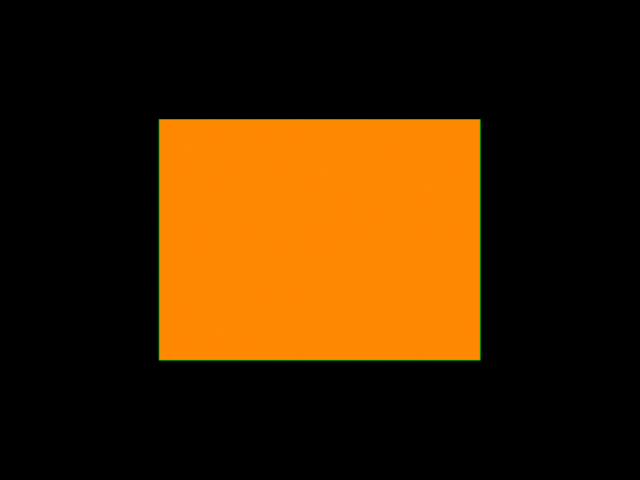
| このコードを、「Rectangle.svg」という新しいテキスト ファイルで 3ds Max UserScripts フォルダに保存します。 次に、Vector_Map テクスチャ マップを作成し、このコードをベクトル ファイルとしてロードします。 次に、生成されるマップを 160x160、320x320 および 640x320 の異なる解像度でビットマップにレンダリングします。 これは、手動で、または MAXScript を使用して実行できます。
|
theSVGMap = VectorMap()
theSVGMap.vectorfile = GetDir #userscripts + "\\rectangle.svg"
for i in #([160,160], [320,320], [640,480]) do
  display (renderMap theSVGMap size:i filter:true)
|
| 上記の MAXScript を評価すると、同じスケーラブル グラフィックス定義から解像度の異なる 3 つのイメージがレンダリングされます。 生成されるイメージは以下のとおりです。 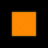 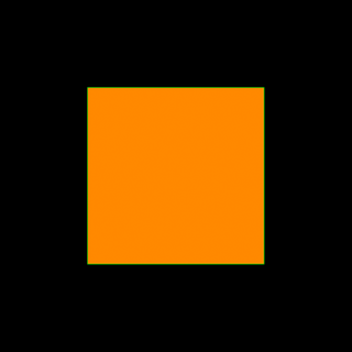
|
SVG ファイルのコンテンツがどのように動作するのかについて説明します。
3ds Max Vector_Map テクスチャ マップは、グラフィックスが描画されるキャンバスのサイズが 1024 x 1024 単位であるものと仮定します。
MAXScript ビットマップ値と同じように、原点[0,0]は左上隅になります。右下隅の座標は[1023,1023]です。
したがって、エンティティの位置およびサイズを指定する場合、キャンバスの中心が[511,511]であると仮定する必要があります。長方形の左上隅を x = 255 および
y = 255 に指定し、幅と高さを 512 単位にすると、長方形はキャンバスの中心に位置合わせされます。
このキャンバス サイズの仮定は 3ds Max に固有のもので、他のソースからの SVG および他のベクトル グラフィックス ファイルには必ずしも適用されません。そのため、Vector_Map
は、エンティティが他の座標で定義された場合に、ラスタライズされたビットマップの部分のみを抽出するためのクロップ コントロールを提供します。
変換の適用
作成した長方形の中心を 45 度回転させてみましょう。
| 変換の例:
|
<svg  xmlns="http://www.w3.org/2000/svg"
      xmlns:xlink="http://www.w3.org/1999/xlink">
    <rect x="255" y="255" height="512" width="512"
          style="stroke:#ff8800; fill: #0000aa"
          transform="rotate(45 511 511)" />
</svg> |
| このコードを、同じ「Rectangle.svg」というテキスト ファイルで 3ds Max UserScripts フォルダに再保存します。 Vector_Map を、マテリアル エディタ内で手動で、または theSVGMap.reload() を使用して MAXScript を介して更新します。
生成されるマップを、解像度 320 x 320 でビットマップにレンダリングします。
|
theSVGMap.reload()
display (renderMap theSVGMap size:[320,320] filter:true) |
| このスクリプトを評価すると、スケーラブルなグラフィックス定義をレンダリングし、ビットマップを表示します。 生成されるイメージは以下のとおりです。 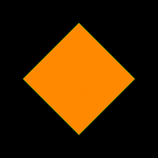
また、シェイプを回転する前に X 軸に沿って 150 単位移動してみます。 複数の変換を指定した場合、それぞれ指定された順序で現在の座標系を変更します。
|
<svg  xmlns="http://www.w3.org/2000/svg"
      xmlns:xlink="http://www.w3.org/1999/xlink">
    <rect x="255" y="255" height="512" width="512"
          style="stroke:#ff8800; fill: #0000aa"
          transform="translate(150) rotate(45 511 511)" />
</svg> |
| SVG 定義を保存し、前述と同じ MAXScript を実行すると、以下が作成されます。 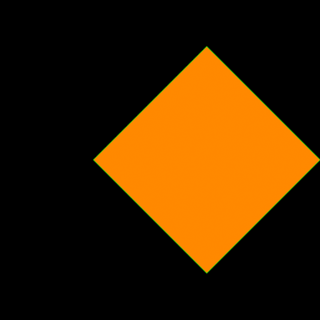
上記の場合、回転の前に平行移動が適用されたため、座標系はまず右にシフトされ、それから回転が実行されました。 平行移動を回転の後で実行するように指定した場合、回転が最初に発生し、平行移動は回転後の座標系内で発生します。
|
<svg  xmlns="http://www.w3.org/2000/svg"
      xmlns:xlink="http://www.w3.org/1999/xlink">
    <rect x="255" y="255" height="512" width="512"
          style="stroke:#ff8800; fill: #0000aa"
          transform="rotate(45 511 511) translate(150)" />
</svg> |
| この場合、X 軸は右下隅を指し、長方形はその方向、すなわち対角線上に 150 単位シフトされます。 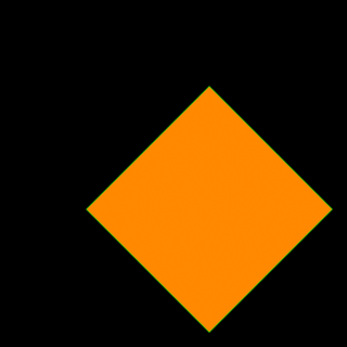
|
文字を作成する
| 文字の例:
|
<svg  xmlns="http://www.w3.org/2000/svg"
  xmlns:xlink="http://www.w3.org/1999/xlink">
  <rect x="255" y="255" height="512" width="512"
    transform="rotate(45 511 511)"
    style="stroke:#ffff00; fill:#001166">
  </rect>
  <text x="255" y="255"
    transform="rotate(45 511 511) translate(15 280)"
    style="stroke:#000000; fill:#008800; font-size:100; font-family:Arial">
    MAXScript
  </text>
</svg> |
| このコードを、「RectangleText.svg」という新しいテキスト ファイルで 3ds Max UserScripts フォルダに保存します。 以下の MAXScript を実行します。
|
theSVGMap = VectorMap()
theSVGMap.vectorfile = GetDir #userscripts + "\\RectangleText.svg"
display (renderMap theSVGMap size:[320,320] filter:true)
|
| このスクリプトを評価すると、以下のイメージをレンダリングします。 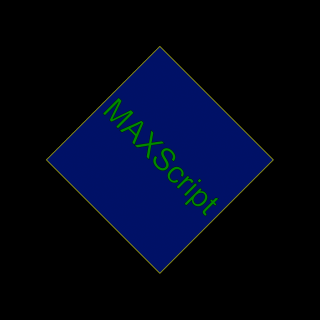
|
グラデーション、ストロークの幅、およびコーナー半径を定義する
シェイプをソリッド カラーで塗り潰す代わりに、名前付きグラデーションを定義し、長方形の fill: パラメータの色の代わりに使用することができます。
このグラデーションには「LinearGradient」という ID があり、不透明度がゼロの濃い青から、不透明度が最大のより明るい青の範囲で、Y 軸に沿って直線的に補間します。
長方形の定義において、「LinearGradient」の ID を使用し、この定義を fill: パラメータに渡します。
さらに、コーナー半径を 30 単位に、長方形とテキストの両方のストローク幅 を 3 単位に設定します。
| グラデーションの例:
|
<svg  xmlns="http://www.w3.org/2000/svg"
  xmlns:xlink="http://www.w3.org/1999/xlink">
  <defs>
    <linearGradient id="LinearGradient1"
      x1="0%" y1="0%"
      x2="0%" y2="100%"
      spreadMethod="pad">
      <stop offset="0%"   stop-color="#001166" stop-opacity="0"/>
      <stop offset="100%" stop-color="#0055aa" stop-opacity="1"/>
    </linearGradient>
  </defs>
  <rect x="255" y="255" height="512" width="512" rx="30" ry="30"
    transform="rotate(45 511 511)"
    style="stroke:#ffff00; fill:url(#LinearGradient1); stroke-width: 10">
  </rect>
  <text x="255" y="255"
    transform="rotate(45 511 511) translate(15 280)"
    style="stroke:#000000; stroke-width:3; fill:#008800; font-size : 100; font-family:Arial">
    MAXScript
  </text>
</svg> |
| このコードを、「RectangleGradientAndText.svg」という新しいテキスト ファイルで 3ds Max UserScripts フォルダに保存します。
以下の MAXScript を実行します。ここでは正確なアルファチャネルを生成するために作成済みのビットマップにレンダリングしています。
|
theSVGMap = VectorMap alphasource:0 --enable Alpha
theSVGMap.vectorfile = GetDir #userscripts + "\\RectangleGradientAndText.svg"
theImage = bitmap 320 320 --create a bitmap with the desired size
renderMap theSVGMap into:theImage filter:true --render into that bitmap
display theImage --display the bitmap
|
| このスクリプトを評価すると、以下のイメージをレンダリングし、アルファ チャネルはグラデーションの不透明度の変化を正しく反映します。 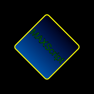 
|
オンライン ドキュメント
SVG フォーマットの公式 Web サイトである http://www.w3.org/Graphics/SVG/ には最新の仕様が掲載されています。
いくつかの SVG の紹介とチュートリアルもオンラインで入手可能です。
MAXScript を使用した SVG ファイルの生成
SVG テキスト ファイルを手動で入力する代わりに、MAXScript の ASCII テキスト ファイル作成機能を使用して SVG ファイルを手順に従って作成することができます。
たとえば、特定の半径および色を持つ円をユーザ定義の位置に出力する関数を作成し、MAXScript の FOR ループを使用して、その関数を複数回を呼び出してみましょう。
また、MAXScript のカラー値を、XML および HTML で使用される 16 進のカラー値に変換する関数も必要です。
注:SVG ファイル内では、「ダブルクォート」の代わりに「シングルクォート」を使用することができます。そのため、\" のようなエスケープ処理が不要となり、MAXScript
の出力がより単純になります。
| 例:
|
(
--The following function converts a MAXScript color value to a Hexadecimal color value
fn ColorToHex col =
(
	theComponents = #(bit.intAsHex col.r, bit.intAsHex col.g, bit.intAsHex col.b)
	theValue = "#"
	for i in theComponents do
		theValue += (if i.count == 1 then "0" else "") + i
	theValue
)

--The following function outputs a basic circle definition to a given SVG file:
fn createSVGCircle SVGFile pos radius:100 stroke:yellow fill:red thick:1 =
(
	format "<circle cx='%' cy='%' r='%' \n" pos.x pos.y radius to:SVGFile
	format "\tstyle='stroke:%; fill:%; stroke-width:%' >\n" (ColorToHex stroke) (ColorToHex fill) thick to:SVGFile
	format "</circle>\n" to:SVGFile
)

theSVGFilename = GetDir #userScripts + "\\Circles.svg" --Define an output file name
theSVGFile = createFile theSVGFilename --Create a text file
format "<svg xmlns=\"http://www.w3.org/2000/svg\"\n" to:theSVGfile --Output the SVG header lines
format "\t\txmlns:xlink=\"http://www.w3.org/1999/xlink\">\n" to:theSVGfile

theStep = 100 --This is the step in pixels along both X and Y
for y = 0 to 1024 by theStep do --Loop along Y and X with the given Step
	for x = 0 to 1024 by theStep do --and create circles with position and fill color based on the loops:
		createSVGCircle theSVGFile [x,y] radius:(theStep/2) stroke:white fill:(color (x/4) (y/4) 100) thick:5

format "</svg>\n" to:theSVGfile --End of the SVG body definition
close theSVGfile --Close the file

theSVGMap = VectorMap() --Create a new Vector_Map instance
theSVGMap.vectorFile = theSVGFilename --Assign the output file to the new map
display (renderMap theSVGMap size:[512,512] filter:true) --Render the map at 512 resolution and display
) |
| ここに、作成されるマップをイメージとしてレンダリングしたものを示します。 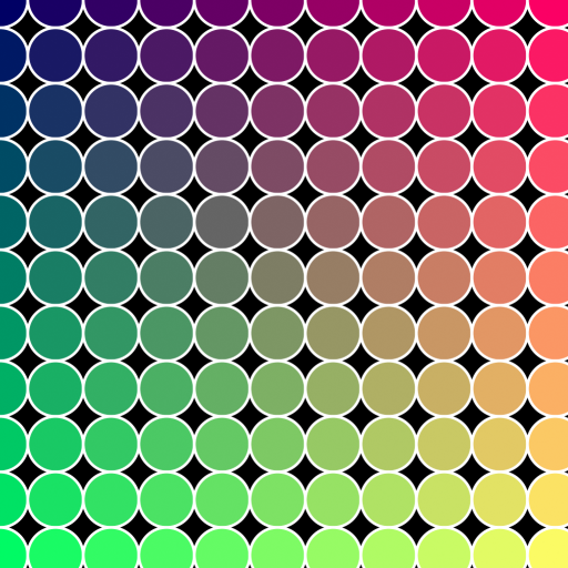 ステップ変数を 100 から 50 に変更するだけで、より多くのサイズの小さい円を簡単に生成することができます。 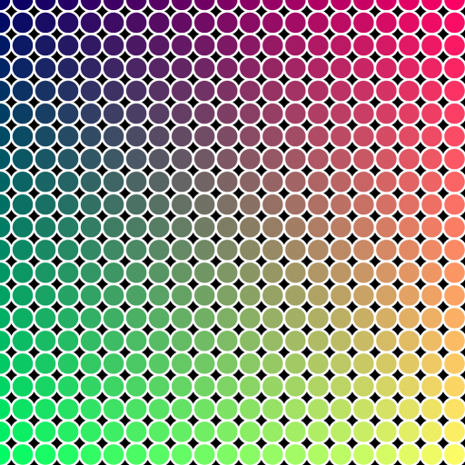
|
| ループをさらに修正してみます。1 行おきに 1/2 ステップ水平方向にシフトし、Y ループを減らして使用するステップを 1/2 にします。 また、ストロークの厚さを 2 にして、細かいアウトラインを生成します。
|
--Partial Code Fragment - insert in the above script!
theStep = 50
cnt = 0 --introduce a counter variable
for y = 0 to 1024 by theStep/2 do --divide the vertical step by two
(
	cnt = 1-cnt --change the counter between 0 and 1 after each row
	for x = 0 to 1024 by theStep do --shift the X by half the step multiplied by the counter (0 or 1):
	(
		createSVGCircle theSVGFile [x+(theStep/2*cnt),y] radius:(theStep/2) stroke:white fill:(color (x/4) (y/4) 100) thick:2
	)
)
--End Code Fragment |
| 結果は魚のウロコのようになりました。 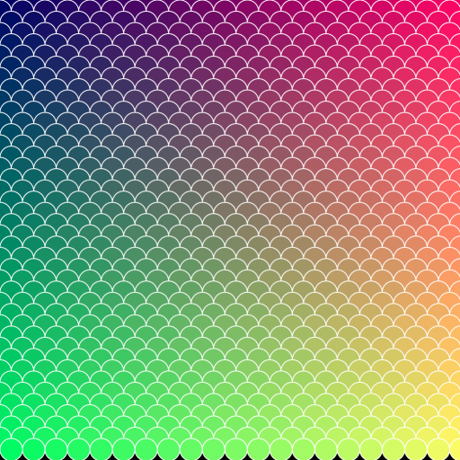
|
静的なシーン プロパティを含める
MAXScript はシーン オブジェクトのプロパティを簡単に読み込むことができるので、SVG にシーンジオメトリ(例えばスプライン シェイプ)を出力し、3ds Max
ビューポートを簡易 SVG エディタに変えることができました。
例えば、上記の円の描画関数を基に、長方形や楕円などの代表的なシェイプについて同様の関数を実装することができます。
続いて、3ds Max のシーンを実行、一致するスプライン プリミティブに遭遇したら、そのプロパティを取得して、SVG ファイルに出力することができます。
| 例:
|
(
fn ColorToHex col =
(
	theComponents = #(bit.intAsHex col.r, bit.intAsHex col.g, bit.intAsHex col.b)
	theValue = "#"
	for i in theComponents do
		theValue += (if i.count == 1 then "0" else "") + i
	theValue
)

fn getFillColor obj =
(
	if classof obj.material == Standard then
		obj.material.diffusecolor
	else
		obj.wirecolor
)

fn getPos obj =
(
	[obj.pos.x, -obj.pos.y]
)

fn createSVGCircle SVGFile pos radius:100 stroke:yellow fill:red thick:1 =
(
	format "<circle cx='%' cy='%' r='%' \n" pos.x pos.y radius to:SVGFile
	format "\tstyle='stroke:%; fill:%; stroke-width:%' >\n" (ColorToHex stroke) (ColorToHex fill) thick to:SVGFile
	format "</circle>\n" to:SVGFile
)

fn createSVGEllipse SVGFile pos rx:100 ry:50 stroke:yellow fill:green thick:1 =
(
	format "<ellipse cx='%' cy='%' rx='%' ry='%'\n" pos.x pos.y rx ry to:SVGFile
	format "\tstyle='stroke:%; fill:%; stroke-width:%' >\n" (ColorToHex stroke) (ColorToHex fill) thick to:SVGFile
	format "</ellipse>\n" to:SVGFile
)

fn createSVGRect SVGFile pos w:100 h:100 rx:0 stroke:yellow fill:blue thick:1 =
(
	format "<rect x='%' y='%' width='%' height='%' rx='%' ry='%'\n" pos.x pos.y w h rx rx to:SVGFile
	format "\tstyle='stroke:%; fill:%; stroke-width:%' >\n" (ColorToHex stroke) (ColorToHex fill) thick to:SVGFile
	format "</rect>\n" to:SVGFile
)

fn createSVGText SVGFile pos textString:"SVG" fontSize:100 stroke:green fill:orange thick:1 =
(
	format "<text x='%' y='%'\n" pos.x pos.y to:SVGFile
	format "\tstyle='font-size:%; font-family:Arial; stroke:%; fill:%; stroke-width:%' >\n" fontSize (ColorToHex stroke) (ColorToHex fill) thick to:SVGFile
	format "%</text>\n" textString to:SVGFile
)

theSVGFilename = GetDir #userScripts + "\\MaxShapes.svg"
theSVGFile = createFile theSVGFilename
format "<svg xmlns=\"http://www.w3.org/2000/svg\"\n" to:theSVGfile
format "\t\txmlns:xlink=\"http://www.w3.org/1999/xlink\">\n" to:theSVGfile

for obj in objects do
(
	local o = obj.baseobject
	if superclassof o == Shape do
	(
		case classof o of
		(
			Circle: createSVGCircle theSVGFile [obj.pos.x,-obj.pos.y] radius:o.radius stroke:obj.wirecolor fill:(getFillColor obj) thick:o.thickness
			Ellipse: createSVGEllipse theSVGFile [obj.pos.x,-obj.pos.y] rx:(o.width/2) ry:(o.length/2) stroke:obj.wirecolor fill:(getFillColor obj) thick:o.thickness
			Rectangle: createSVGRect theSVGFile [obj.min.x,-obj.max.y] w:o.width h:o.length rx:o.cornerRadius stroke:obj.wirecolor fill:(getFillColor obj) thick:o.thickness
			Text: createSVGText theSVGFile [obj.min.x,-obj.min.y] textString:o.text fontSize:o.size stroke:obj.wirecolor fill:(getFillColor obj) thick:o.thickness
		)
	)
)
format "</svg>\n" to:theSVGfile
close theSVGfile

theSVGMap = VectorMap()
theSVGMap.vectorFile = theSVGFilename
display (renderMap theSVGMap size:[512,512] filter:true)
) |
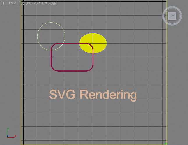
| 以下のスクリーンショットは、緑色の円、濃い赤色の長方形、紫色の楕円、およびオレンジ色のテキストを含むシーンです。 円の半径は 100 で、マテリアルとモディファイヤはありません。 長方形は 300x200 単位で、コーナーの半径は 50 です。そのレンダリング可能なプロパティがチェックされ、厚さは 5 で、青色の拡散反射光カラーが割り当てられた標準マテリアルがあります。
サイズが 200x150 の楕円は、厚さが 10 に設定され、スタックには MeshSelect モディファイヤがあり、黄色の標準マテリアルが割り当てられています。
テキストにマテリアルはなく、スタックに MeshSelect モディファイヤがあります。 これらのオブジェクトは元のワールド座標の右下の四半円に配置され、その Y 座標はマイナスとなり、原点は左上隅になります。緑色のポイント ヘルパーは、[1023,1023]座標の位置を示します。
 上記のスクリプトを実行すると、次のイメージが生成されます。 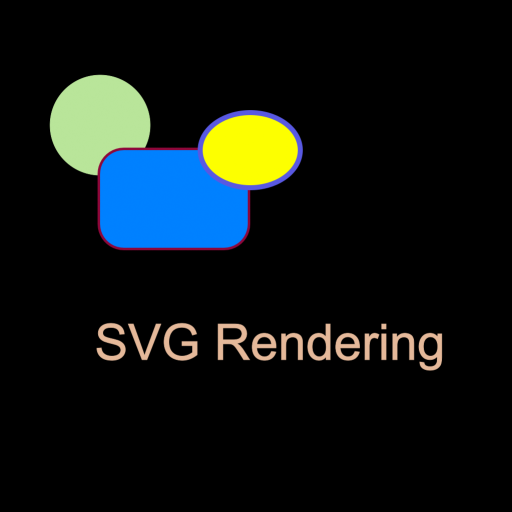 シェイプの描画の順序は、オブジェクトの作成の順序を反映していることに注意してください。ストローク カラーはワイヤフレーム(オブジェクト)の色から取られています。マテリアルが存在しなかった場合、塗り潰しカラーは標準マテリアルの拡散反射光カラー、あるいはワイヤ
カラーのプロパティから取られています。レンダリング可能な厚さプロパティも適用されました。
上記のスクリプトは回転を考慮していません。回転をサポートするためには、3ds Max と SVG 間の座標系およびオブジェクトのピボット ポイントの違いのために、大きな変更が必要であることに注意してください。
|
外部ファイルなしで SVG 定義を設定する
Vector_Map テクスチャ マップは専用のメソッド .SetSvgString() を提供します。これは、ディスク上のファイルを参照するのではなく、文字列値として SVG XML 定義を渡すために使用することができます。
これは、MAXScript が列変数または StringStream 内で完全な SVG 記述を構築し、それを直接 Vector_Map に渡すことができることを意味します。
SVG ファイルでの MX トークンの使用
MAXScript は SVG ファイルの生成に使用できるだけでなく、3ds Max Vector_Map テクスチャ マップには、SVG ファイル自体に埋め込まれた MAXScript コードに対する拡張サポートも含まれています。
MAXScript 式の結果が String 値である限り、特殊な mxs トークン(MAXScript の省略形)を SVG ファイル内で使用して、XML の記述に含めることができます。
これは、SVG マップを MAXScript および 3ds Max とより深く統合できる可能性を示しています。
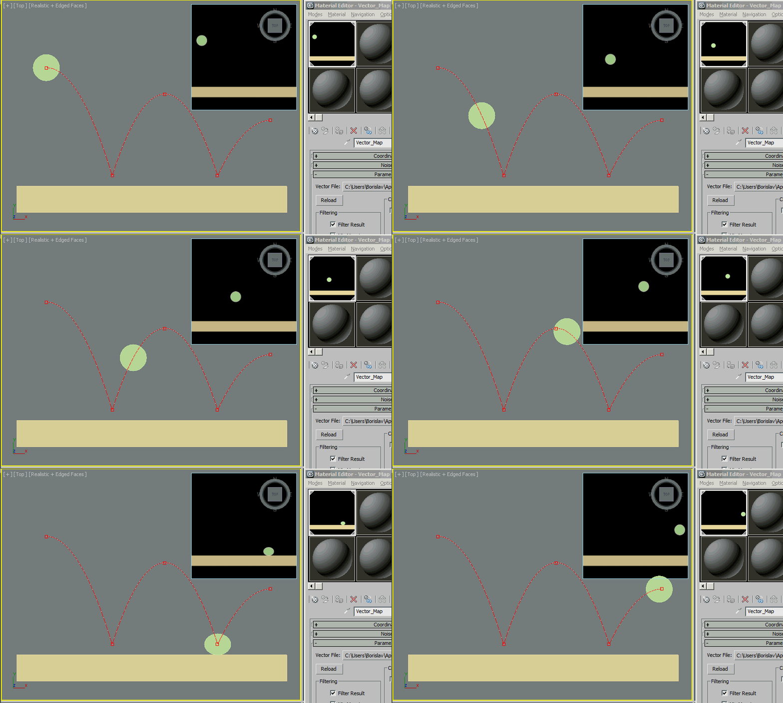
SVG オブジェクトは 3ds Max シーン値にダイナミックにアクセスできるだけでなく、Vector_Map を時間の変化とともに更新し、アニメートされたシーン パラメータに基づいてアニメートされたマップを作成できます。
| アニメートされた SVG の例:
|
<svg xmlns="http://www.w3.org/2000/svg"
		xmlns:xlink="http://www.w3.org/1999/xlink">
<rect x='0.0' y='800.0' width='1024.0' height='100.0'
	style='stroke:#e4d699; fill:#e4d699; stroke-width:1.0' >
</rect>
<ellipse cx='mxs(at time currentTime $Ellipse001.pos.x as string)'
	cy='mxs(at time currentTime (-$Ellipse001.pos.y) as string)'
	rx='mxs(at time currentTime ($Ellipse001.width/2) as string)'
	ry='mxs(at time currentTime ($Ellipse001.length/2) as string)'
	style='stroke:#ffffff; fill:#b8e499; stroke-width:3.0' >
</ellipse>
</svg> |
| 上記の SVG ファイルを保存し Vector_Map を使用してロードすると、Ellipse001 オブジェクトの位置および半径アニメーションに従うアニメートされたテクスチャがシーン内に生成されます。
標準マテリアルの拡散反射光チャネルにその Vector_Map テクスチャを割り当て、平面にそれを割り当てると、ビューポート内にダイナミックなリアルタイムのレンダリング「画面」が生成され、同じアニメーションを表示します。さらに、マテリアル
エディタ内のマップ表示はアニメーションのレンダリングと表示も実行します。
|
SVG ファイルに MAXScript .MS ファイルを含める
インラインの MAXScript 式を使用する代わりに、SVG ファイル内の mxs() トークンには、外部 .MS ファイルに定義された MAXScript 関数への関数呼出しを含めることができます。これは、計算がより複雑な場合、またはスクリプト コードを頻繁に修正する必要があり、SVG
定義から MAXScript 計算を切り離す方が便利な場合に最も理にかなっています。
SVG ファイルは、その外部 .MS ファイルを引数として MAXScript の include() 関数を一度のみ呼び出す必要があります。これで、その中に定義された関数が SVG の本文の残りの部分からアクセス可能になり、 mxs() を介して呼び出されるようになります。これらの関数は、SVG ストリームに含めることができるよう、文字列値を返さなければなりません。
注: include() 呼び出しでは、ファイル名に二重引用符が必要です。 include() 呼び出しを SVG プロパティ値の中に挿入する必要がある場合、SVG 値は MAXScript 呼び出しと共存するために単一引用符で囲む必要があります。
| MAXScript インクルード ファイル:
|
fn getUserName =
(
	sysinfo.username --this is already a string
)
fn getComputerName =
(
	sysinfo.computername --this is already a string
)
fn getNumCPUs =
(
	sysinfo.cpucount as string --this is an Integer, so needs conversion to string
) |
| 上記のコードを UserScripts フォルダ(getDir #userscripts)内の「TextIncludeFn.ms」に保存します。
|
| SVG ファイル:
|
<svg  xmlns="http://www.w3.org/2000/svg"
  xmlns:xlink="http://www.w3.org/1999/xlink">
  <text x='100' y='300'
    style='stroke:#00FF88; fill:#005588; font-size:70; font-family:Arial'>
    Hello mxs(include "TextIncludeFn.ms" getUserName())!
  </text>
  <text x='100' y='400'
    style='stroke:#00FF88; fill:#005588; font-size:70; font-family:Arial'>
    Your Computer mxs(getComputerName())
  </text>
  <text x='100' y='500'
    style='stroke:#00FF88; fill:#005588; font-size:70; font-family:Arial'>
    has mxs(getNumCPUs()) CPUs
  </text>
</svg> |
| 上記の SVG 定義を .MS ファイルと同じフォルダ(getDir #userscripts)に「TextIncludeFn.svg」として保存します。 getUserName() を最初に使用する前に include() 呼び出しが一度だけ実行され、追加の mxs 関数呼び出しには、.MS ファイルを再度含める必要がありません。
|
| ベクトル マップのテクスチャ マップ作成:
|
theVMap = VectorMap() --create a vector map
theSVGFileName = GetDir #userScripts + "\\TextIncludeFn.svg" --define the file name of the SVG map source
theVMap.vectorfile = theSVGFileName --assign the SVG file to the map
theTextImage = bitmap 512 512 --create an image for the text
renderMap theVMap into:theTextImage filter:true --render the Vector Map into the image
display theTextImage --display the resulting image |
| 結果の例:
|

|
SVG を使用してテキストをビットマップにレンダリングする
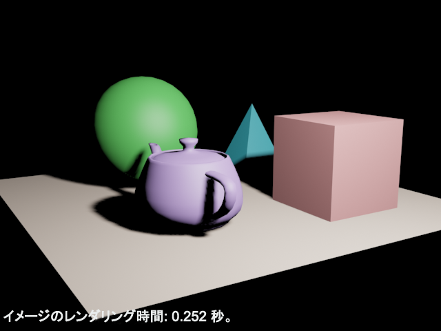
以下の例では、Vector_Map テクスチャ マップのテキスト レンダリング機能を使用してレンダリング時間情報を含むビットマップを生成します。
renderMap() 関数を使用してビットマップを作成し、 render() 関数を使用して生成されたイメージ上に重ねます。
| 例:
|
renderW = 640 --define the render output width
renderH = 480 --define the render output height
textSize = 20 --define the overlay text's height in pixels
theImage = bitmap renderW renderH --define a bitmap for the render output
st = timestamp() --get a timestamp before rendering
render to:theImage vfb:off --render the scene into the existing bitmap
et = timestamp() --get a time stamp after rendering
theTime = "Image Render Time: " +((et-st)/1000.0) as string + " seconds." --define the text to overlay
theVMap = VectorMap() --create a vector map
theSVGFileName = GetDir #userScripts + "\\RenderInfoMap.svg" --define the file name of the SVG map source
theSVGFileHandle = createFile theSVGFileName --create a new text file with that name
format "<svg xmlns=\"http://www.w3.org/2000/svg\"\n" to:theSVGFileHandle --define the svg header
format "\txmlns:xlink=\"http://www.w3.org/1999/xlink\">\n" to:theSVGFileHandle
format "\t<text x='0' y='%'\n" textSize to:theSVGFileHandle --define the text position
format "\t\tstyle='font-size : %;\n" textSize to:theSVGFileHandle --define the text font size
format "\t\tfont-family: Arial; \n" to:theSVGFileHandle --define the text font family
--format "\t\tstroke: #ffffff;\n" to:theSVGFileHandle --define the text outline. Bad Idea, makes it too thick
format "\t\tfill: #ffffff\n" to:theSVGFileHandle --define the fill color of the text as white
format "\t\t'\n" to:theSVGFileHandle --close the font style definition
format "\t>%</text>\n" theTime to:theSVGFileHandle --output the text to display
format "</svg>\n" to:theSVGFileHandle --end the SVG definition
close theSVGFileHandle --close the SVG file
theVMap.vectorfile = theSVGFileName --assign the SVG file to the map
theVMap.alphasource = 0 --enable Alpha output
theTextImage = bitmap 1000 1000 --create an image for the text
renderMap theVMap into:theTextImage filter:true --render the Vector Map into the image
--composite the text from the image onto the rendered image
pasteBitmap theTextImage theImage (box2 0 0 1000 (textSize*2.0)) [5,renderH-(textSize*1.5)] type:#composite
display theImage --display the result |
| 結果の例:
|
|
SVG と Vector_Map についての詳細
「チュートリアル」セクションの 3 部からなるチュートリアルでは、Vector_Map と SVG フォーマットを使用してジオメトリ オブジェクトをポリゴンとしてレンダリングする方法について説明しています。


