In this exercise, you will create a three-way junction and generate a corridor that maintains the crowns of both roads.
To create a complete junction model, you must have a centerline alignment and profile for each of the intersecting roads. The horizontal and vertical geometry for the remaining elements, including the offsets and corner radius, is generated based on the parameters you specify.
In a peer road junction, the crowns of all intersecting roads are held at a common gradient. The pavement for both roads is blended into the corner radius regions, which form the transitions between the intersecting roads.
The drawing for this exercise contains a corridor along each of the intersecting roads. Each corridor is made up of a corridor assembly and a centerline alignment and profile.
At the end of the exercise, the drawing also will contain the following elements:
- A junction object
- Two corner radius alignments and profiles
- Four offset alignments and profiles (two for each centerline alignment)
- Several new corridor regions
- Corridor assemblies for each region of the junction
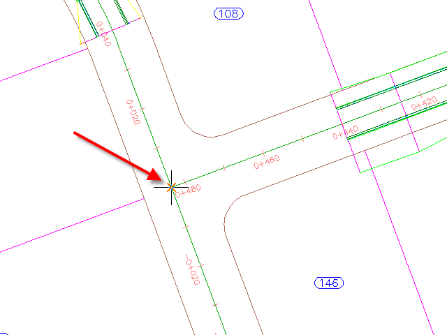
Specify the junction location
- Open Junction-Create-1.dwg, which is located in the tutorials drawings folder.
- Click tab
 panel drop-down Find.
 - In the drawing, click the junction point of the two alignments.
Specify the corridor gradient parameters
- In the Create Junction wizard, on the General page, under Junction Corridor Type, select All Crowns Maintained.
- Click Next.
Specify the geometry of the offsets and corner radius
- On the Geometry Details page, click Offset Parameters.
Default parameters are stored in the drawing settings. You can modify the default parameters during the junction creation process.
- In the Offset Parameters dialog box, specify the following parameters:
- Secondary RoadLeft Offset Alignment DefinitionOffset Value: 3.5000
- Secondary RoadRight Offset Alignment DefinitionOffset Value: 3.5000
- Create New Offsets From Start To End Of Centerlines: Cleared
When this option is selected, offset alignments are created along the entire length of the centerline alignment. This option is useful when you need to use offset alignments and profiles as targets for other objects, including other junctions along the same road.
- Secondary Road
- Click OK.
- On the Geometry Details page, click Radius Kerb Parameters.
- In the Junction Corner Radius dialog box, under Corner Radius Parameters, specify the following parameters:
- Corner Radius Type: Circular Fillet
- Radius: 7.5
Note:In the drawing, temporary graphics highlight the currently selected corner radius.
- Right-click Corner Radius Parameters. Click Copy These To All Quadrants.
This command copies the corner radius parameters to all junction corner radius regions. The number of corner radius regions is automatically generated based on the existing horizontal geometry. For example, if this was a four-way junction, four corner radius regions would be available.
- Click OK.
- In the Create Junction wizard, under Offset And Corner Radius Profiles, make sure that Create Offset And Corner Radius Profiles is selected.
To produce a complete corridor model of the junction, it is necessary to create profiles for the offset alignments and corner radius alignments. For this exercise, you will accept the default offset and corner radius profile settings.
- Click Next.
Specify the corridor parameters
- On the Corridor Regions page, specify the following options:
- Create Corridors In The Junction Area: Selected
- Add To An Existing Corridor: Selected, Second Street
- Select Surface To Daylight: EG
- Under Select Assembly Set To Import, click Browse.
- In the Select Assembly Set File dialog box, navigate to the tutorial folder.
- Select Junction-Assembly-Set_All Crowns.xml. Click Open.
An assembly set enables you to quickly import a group of existing corridor assemblies, and then apply them to specific section types.
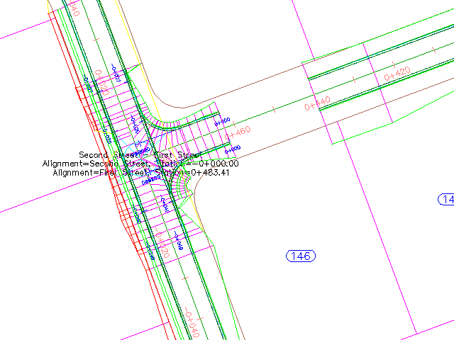
- Click Create Junction.
The junction is created, and new corridor regions are created in the junction area.
Examine the new objects
- In Toolspace, on the Prospector tab, expand the
 Alignments collection.
 Four alignments collections are available.
- Under Alignments, expand the Centerline Alignments,
 Offset Alignments, and
  Corner Radius Alignments collections.
 At the beginning of this exercise, only Centerline Alignments existed. The Offset Alignments and Nearside Kerb Alignments were created using the parameters that you specified in the Create Junction wizard.
Note:In the drawing, the offset alignments and chainage labels are blue, and the nearside kerb alignments are red.
- Under Offset Alignments, expand the First Street-Left-3.500
 Profiles collection.
 Layout profiles for the Offset Alignments and Nearside Kerb Alignments were created using the parameters that you specified in the Create Junction wizard.
Closing gaps in the corridor
- In the drawing, select the corridor in the junction area.
Slider
 grips are displayed at the start and end chainages of the corridor regions.
 - Click the grip at chainage 0+040.
The grip turns red.
- On the command line, enter 21.
- Click Corridor tab Modify Region panel Copy Region Find.
- Select the portion of the Second Street corridor that loops around the site.
- On the command line, enter F to fill a gap in the corridor.
- Move the cursor toward the gap in the corridor.
A red graphic indicates that the gap may be filled.
- Click when the red graphic is visible.
The gap is filled.
- Press Enter to end the command.
- Click Corridor tab Modify Corridor panel Rebuild Corridor Find.
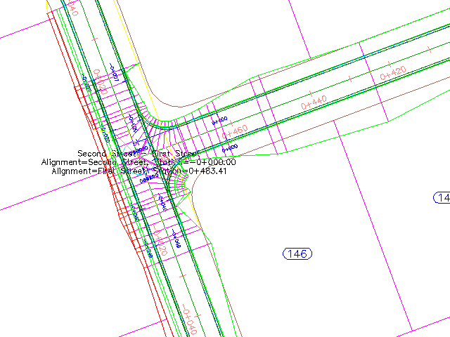
The Second Street corridor rebuilds, eliminating the gaps.
- Select the First Street corridor. Select the grip at Chainage 0+440.
The grip turns red.
- Drag the grip toward the junction. Click to place the grip at the beginning of the junction.
- Right-click the First Street corridor. Click Rebuild Corridor.
The corridor rebuilds, eliminating the gaps between it and the junction.
To continue this tutorial, go to Exercise 2: Creating a Primary Road Junction with Turning Lanes.