In this exercise, you will create a junction with entry and exit turning lanes at the primary road. The side road crown will blend into the primary road edge of pavement.
You can use the workflow that is demonstrated in this exercise to create a junction with any combination of turning lanes at the radius kerbs.
Specify the junction location and primary road
- Open Intersection-Create-2.dwg, which is located in the tutorials drawings folder.
- Click tab
 panel drop-down Find.
 - In the drawing, click the junction point of the Road A and Road B alignments.
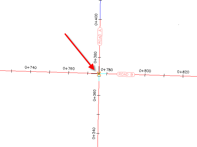
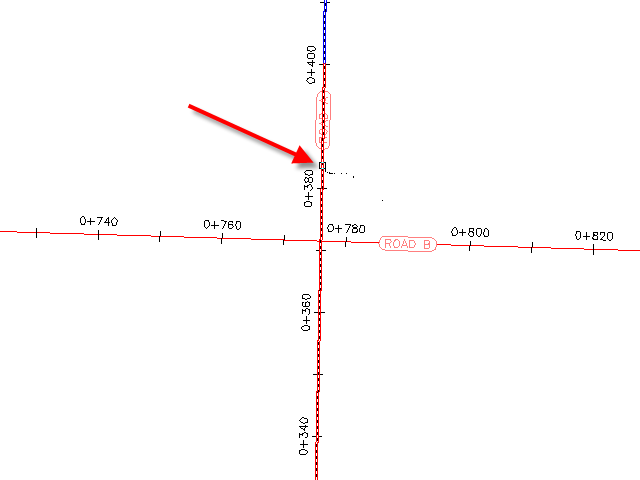
- Click the Road A alignment to specify it as the primary road.
Specify the corridor gradient parameters
- In the Create Junction wizard, on the General page, under Junction Corridor Type, select Primary Road Crown Maintained.
- Click Next.
Specify the horizontal and vertical geometry parameters
- On the Geometry Details page, click Offset Parameters.
Default horizontal and vertical geometry parameters are stored in the drawing settings. You can modify the default parameters during the junction creation process.
- In the Offset Parameters dialog box, specify the following parameters:
- Primary RoadLeft Offset Alignment DefinitionOffset Value: 6.0000
- Primary RoadRight Offset Alignment DefinitionOffset Value: 6.0000
- Secondary RoadLeft Offset Alignment DefinitionOffset Value: 3.0000
- Secondary RoadRight Offset Alignment DefinitionOffset Value: 3.0000
- Create New Offsets From Start To End Of Centerlines: Selected
- Primary Road
- Click OK.
- On the Geometry Details page, click Radius Kerb Parameters.
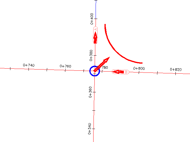
The default parameters for the first junction quadrant are displayed in the Junction Radius Kerb Parameters dialog box. In the drawing, the first quadrant is highlighted, and arrows indicate the direction of incoming and outgoing traffic.
Note:If you cannot see the temporary graphics, move the dialog box.
- In the Junction Radius Kerb dialog box, select the Widen Turning Lane For Outgoing Road check box.
The Widening Details At Outgoing Lane parameter collection is displayed in the property tree. When you highlight a property, the preview graphic at the bottom of the dialog box updates to illustrate the property in a typical junction. Examine the default values that have been specified for this drawing, but do not change any of them.
- Click Next.
- For SE - Quadrant, select the Widen Turning Lane For Incoming Road check box.
- Click Next.
- For SW - Quadrant, select the Widen Turning Lane For Outgoing Road check box.
- Click Next.
- For NW - Quadrant, select the Widen Turning Lane For Incoming Road check box.
- Click OK.
- In the Create Junction wizard, make sure that the Create Offset And Radius Kerb Profiles check box is selected.
- Click Next.
Specify the corridor parameters
- On the Corridor Regions page, specify the following options:
- Create Corridors In The Junction Area: Selected
- Create A New Corridor: Selected
- Select Surface To Daylight: Existing Ground
- In the Select Assembly Set File dialog box, navigate to the Assemblies folder.
- Select _Autodesk (Metric) Assembly Sets.xml. Click Open.
- Under Maintain Priority Road Crown, in the Radius Kerb Fillets row, click
 .
. You can use the Select An Assembly dialog box to substitute an assembly with another assembly that is in the current drawing. To save your changes as a new assembly set, click Save As Set on the Corridor Regions page. For this exercise, you will accept the default assembly set.
For more information about managing corridor assemblies, see the Corridor Assembly Tutorials.
- Click Cancel.
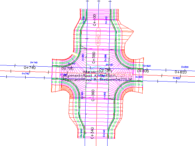
- Click Create Junction.
The junction is created, and new corridor regions are created in the junction area. Notice that the radius kerbs have widening regions to allow traffic to exit from and merge onto Road A.
To continue this tutorial, go to Exercise 3: Creating a Junction with Existing Geometry.