In this exercise, you will edit the alignments that define the horizontal geometry of a junction. You will edit the alignments graphically and parametrically, and then examine how the changes affect the junction.
Modify offset alignment parameters
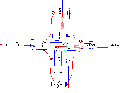
- Open Intersection-Edit-Horizontal.dwg, which is located in the tutorials drawings folder.
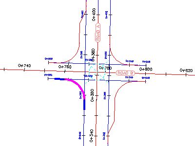
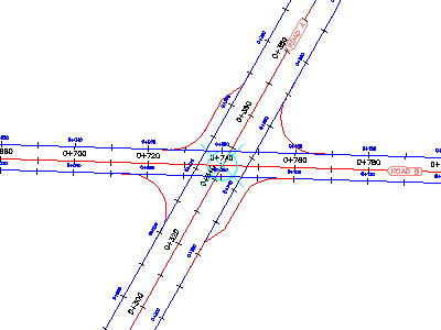
This drawing contains a junction of a primary road (Road A) and a side road (Road B).
- The offset alignments for Road A extend along the full length of the centerline alignment.
- The offset alignment for Road B does not extend beyond the junction extents.
- The radius kerbs have widening regions on all four corners of Road A.
- Click the junction marker.
The Junction tab is displayed on the ribbon. The Modify panel has tools that you can use to modify the parameters of the horizontal and vertical geometry of the junction.
- Click tab
 panel Find.
 The offset alignment parameters are displayed in the Junction Offset Parameters dialog box.
- Under Side Road, change the Offset Value for both offset alignments to 4.000.
Notice that as the values change, the junction updates in the drawing.
Modify the radius kerb parameters
- Click tab panel Find.
The Junction Radius Kerb Parameters dialog box displays the nearside kerb alignment parameters for the northeast junction quadrant. This dialog box enables you to change basic parameters, as well as specific details of the radius kerb at each junction quadrant.
In the drawing, notice that the currently selected radius kerb is highlighted.
- Clear the Widen Turning Lane For Outgoing Road check box.
In the drawing, the widening region for the northeast quadrant is removed.
- Under Junction Quadrant, click SW - Quadrant.
- Clear the Widen Turning Lane For Outgoing Road check box.
Grip edit a nearside kerb alignment
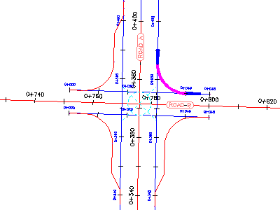
- In the drawing, select the southeast nearside kerb alignment.
Grips appear along the nearside kerb alignment.
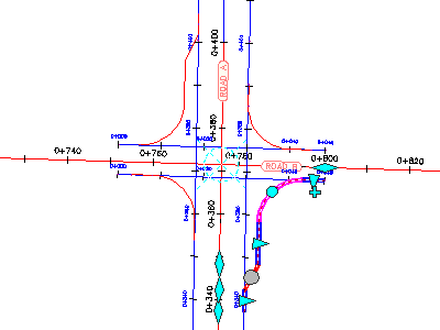
- On the Road A alignment, experiment with the
 grips.
 When you move a grip, the radius kerb widening region updates, and the values update in the Junction Radius Kerb Parameters dialog box.
- Press Esc.
Grip edit the centerline alignments
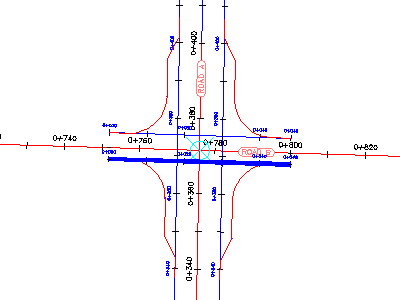
- Select both offset alignments along Road B.
- Click the grip on the left. Drag the grip to the left. Click near chainage 0+660 to place the grip.
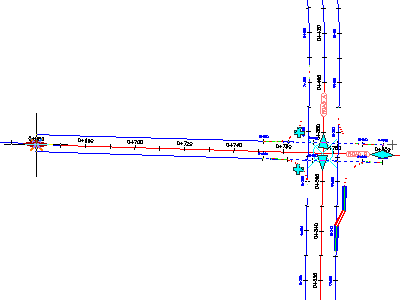
This action enables the relationship between the radius kerbs and the offset alignments to be maintained as you move the junction along the centerline alignment.
- Press Esc.
- Zoom out to see the ends of both centerline alignments.
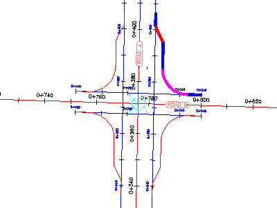
- Select the Road A centerline alignment.
- Select the grip at the southern end of the alignment.
- Drag the grip to the left. Click to place the grip.
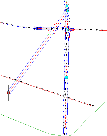
The junction slides along the Road B centerline and offset alignment. The nearside kerb alignments and Road A offset alignments move to accommodate the new junction point. The radius kerb and offset alignment geometry parameters are maintained.
To continue this tutorial, go to Exercise 2: Editing the Vertical Geometry of an Intersection.