In this exercise, you will use the criteria-based design tools to create an alignment that complies with specified standards.
This exercise is divided into two parts:
- First, you will specify design criteria for an alignment as you create it, and then draw a series of alignment elements that violate the design criteria. You will correct the violations in Exercise 2: Viewing and Correcting Alignment Design Criteria Violations.
- Second, you will create an alignment element that meets the design criteria specified in the design criteria file. You will use the minimum default values that are displayed on the command line to ensure that the element meets the specified design criteria.
Specify design criteria for an alignment
- Open Align-7A.dwg, which is located in the tutorials drawings folder.
The drawing contains a surface marked with several circles, labeled A through E.
Note:Ensure that Object Snap (OSNAP) is turned on. For more information, see Object Snapping.
- Click tab
 panel drop-down Find.
- In the Create Alignment – Layout dialog box, accept the default values for Name and Starting Chainage. Leave the Description field blank for this exercise.
- On the General tab, specify the following parameters:
- Site: <None>
- Alignment Style: Design Style
- Alignment Layer: C-ROAD
- Alignment Label Set: Major Minor and Geometry Points
- On the Design Criteria tab, for Starting Design Speed, enter 50 km/h.
This speed will be applied to the starting chainage of the alignment. You can add design speeds as needed to other stations. A design speed is applied to all subsequent stations until either the next chainage that has an assigned design speed or the alignment ending chainage.
- Select the Use Criteria-Based Design check box.
When this option is selected, the criteria-based design tools are available. There are two check boxes that are selected by default:
-
Use Design Criteria File
—The design criteria file is an XML file that contains minimum design standards for alignment and profile objects. The design criteria file can be customized to support local design standards for design speed, superelevation, and minimum speed, radius, and length of individual elements. The Default Criteria table lists the properties that are included in the default design criteria file, the location of which is displayed in the field above the Default Criteria table.
You will learn more about the design criteria file in Exercise 4: Modifying a Design Criteria File.
- Use Design Check Set —Design checks are user-defined formulas that verify alignment and profile parameters that are not contained in the design criteria file. Design checks must be included in a design check set, which is applied to an alignment or profile.
-
Use Design Criteria File
—The design criteria file is an XML file that contains minimum design standards for alignment and profile objects. The design criteria file can be customized to support local design standards for design speed, superelevation, and minimum speed, radius, and length of individual elements. The Default Criteria table lists the properties that are included in the default design criteria file, the location of which is displayed in the field above the Default Criteria table.
- In the Use Design Criteria File area, click
 .
.
- In the Select Design Speed Table dialog box, select _Autodesk Civil 3D Metric Roadway Design Standards.xml. Click Open.
Note: There are multiple design criteria files available to choose from. This exercise uses the AASHTO 2001 standards which are provided in _Autodesk Civil 3D Metric Roadway Design Standards.xml. If you select the 2004 or 2011 file, please note that you may see somewhat different values than what are shown and described in this tutorial.
You will learn about creating a custom design criteria file in Exercise 4: Modifying a Design Criteria File.
- In the Default Criteria table, in the Minimum Radius Table row, change the Value to DMRB 2001 eMax 6%.
- In the Use Design Check Set list, select 50kmh Roadway Length Checks. Click OK.
This design check set contains a simple design check. You will create another design check and add it to this design check set in Exercise 3: Working with Design Checks.
Draw alignment elements that meet the specified design criteria
- On the Alignment Layout Tools toolbar, click
 Straight-Straight (No Curves).
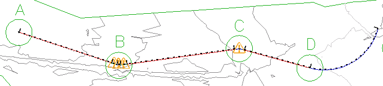
- Snap to the center of Circle A to specify a start point for the alignment. Stretch a line out, and specify additional PIs by snapping to the center of Circles B, C, and D (in order). Then, right-click to end the horizontal alignment layout command.
- On the Alignment Layout Tools toolbar, click
 Free Transition-Curve-Transition (Between Two Elements).
- As prompted on the command line, click the straight element that enters Circle B from the left (the ‘first element’).
- Click the straight that exits Circle B on the right (the ‘next element’).
- Press Enter to accept the default value of a curve solution angle that is less than 180 degrees.
- For radius, enter 75.
Notice that the Specify Radius prompt includes a default value. This value is the minimum acceptable curve radius at the current design speed. The minimum value is contained in the Minimum Radius Table in the design criteria file. You can enter a different value, as long as it is greater than the default minimum value that is displayed. For this exercise, you will use values that do not meet the design criteria, and then examine the results.
- For transition in length, enter 25.
- For transition out length, enter 25.
- In the Alignment Layout Tools toolbar, click the drop-down list
 . Click
  Free Curve Fillet (Between Two Elements, Radius).
- As prompted on the command line, click the straight that enters Circle C from the left (the ‘first element’).
- Click the straight that exits from Circle C on the right (the ‘next element’).
- Press Enter to select the default value of a curve less than 180 degrees.
- Press Enter to select the minimum radius of 90.000m.
- Right-click to end the command.
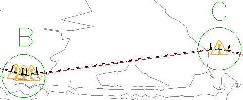
Notice that in the drawing window,
 symbols appear on the curve elements you created. The symbols indicate that the elements violate the specified design criteria. You will learn how to correct these violations in Exercise 2: Viewing and Correcting Alignment Design Criteria Violations.
In step 14, you accepted the minimum radius value specified in the design criteria file, yet a warning symbol is displayed on the curve. This happened because while the curve meets the design criteria specified in the design criteria file, it violates the design check that is in the design check set. You will learn how to correct design criteria and design check violations in the next exercise.
Next, you will add another curve element and examine the results.
Add a sub-element that meets design criteria
- On the Alignment Layout Tools toolbar, click the drop-down list . Select More Floating Curves
 Floating Curve (From Entity End, Radius, Length).
- As prompted on the command line, click the straight element that ends in Circle D (the ‘element to attach to’).
Tip:
The warning symbols do not automatically scale when you zoom in. Enter REGEN on the command line to resize the warning symbols.
- On the command line, enter O to specify the counterclockwise direction.
- Enter a radius value of 200.000m.
- When prompted to specify a curve length, click in the center of Circle D, and then click in the center of Circle E.
The curve is displayed in the drawing. The length value is the distance between the two points that you clicked.
- Right-click to end the command.
Notice that a warning symbol is not displayed on this curve. The radius value you entered in step 4 exceeds the minimum value defined in the minimum radius table that you specified.
To continue this tutorial, go to Exercise 2: Viewing and Correcting Alignment Design Criteria Violations.