In this exercise, you will examine alignment design criteria violations, and then learn how to correct a criteria violation.
When a sub-element violates either a criteria or design check, a warning symbol is displayed on the sub-element in the drawing window, Alignment Elements vista, and Alignment Layout Parameters dialog box. When the cursor is hovered over a warning symbol in the drawing window, a tooltip displays information about the violation. If a design criteria has been violated, the tooltip displays the criteria that has been violated, as well as the minimum value required to meet the criteria. If a design check has been violated, the tooltip displays the name of the design check that has been violated.
This exercise continues from Exercise 2: Drawing a Profile that Refers to Design Criteria.
Check the alignment design for criteria violations
- Open Align-7B.dwg, which is located in the tutorials drawings folder.
- Pan and zoom until you can see Circles B and C on the surface.
Tip:
The warning symbols do not automatically scale when you zoom in. Enter REGEN on the command line to resize the warning symbols.
- Hover the cursor over the middle
 symbol in Circle B.
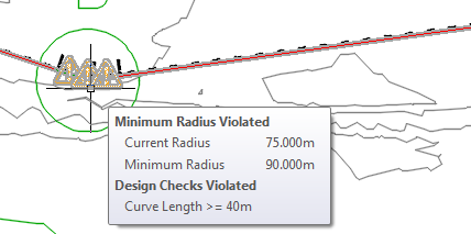
The tooltips are a convenient way to review design criteria violations in the drawing window. Two violations are displayed in the tooltip:
- First, the curve does not meet the recommended minimum radius. The curve radius and minimum acceptable parameter values are both displayed.
- Second, the curve violates a design check that has been applied to the alignment. Notice that the name of the design check is displayed, but not the current or recommended values. Values are not displayed because design checks are custom formulas that are created by the user.
 Note:
Note:If a sub-element violates multiple criteria or design checks, only a single symbol is displayed on the sub-element. To clear a symbol from a sub-element, all the violations must be cleared.
- If the Alignment Layout Tools toolbar is not open, select the alignment. Right-click. Click .
- On the Alignment Layout Tools toolbar, click Alignment Grid View
 .
.
In the Alignment Elements vista, in rows 2.1 through 2.3, a
 warning symbol appears in the No. column, as well as in several other columns. Warning symbols appear next to each value that violates the design criteria that are specified in the design criteria file.
- In row 2.2, hover the cursor over the
 warning symbol in the No. column.
Notice that the tooltip displays the design criteria and design checks that have been violated.
- Hover the cursor over the warning symbol in row 4.
Notice that the name of the design check that has been violated is displayed in the tooltip. Design checks are custom mathematical formulas that return either a true or false value. They indicate whether the applicable elements violate the conditions in the design check, but do not specify how to correct the violation. You will learn more about design checks in Exercise 3: Working with Design Checks.
- On the Alignment Layout Tools toolbar, click Sub-Element Editor
 .
.
The Alignment Layout Parameters window is displayed, containing no data.
- In the Alignment Elements vista, click any row for segment No. 2, which is the transition-curve-transition element in Circle B.
The design data for all three sub-elements is displayed in a three-column table in the Alignment Layout Parameters window, where data is easy to review and edit.
Notice that in the Alignment Layout Parameters window, in the Design Criteria panel, a
symbol is displayed next to each design criteria property that has been violated. In the Layout Parameters panel, the Value column displays the actual parameters of each sub-element. The Constraints column displays the design criteria values that the sub-elements must meet. A symbol is displayed next to each parameter that violates the design criteria. As is true in the drawing window and Alignment Elements Vista, the design check that has been violated is displayed, but individual parameters that violate the check are not marked.
Correct design criteria violations
- In the Alignment Layout Parameters window, on the Layout Parameters panel, change the Transition In Length Value to 33.000m. Press Enter.
Notice that the warning symbol is cleared from the Transition In Length row.
- Change the Transition Out Length Value to 33.000m. Press Enter.
- Change the Curve RadiusValue to 100.000m. Press Enter.
The
warning symbol is cleared from the Curve Radius row, as well as from the Alignment Elements vista.
Notice that the warning symbol is still displayed on all the curve sub-element. The curve still violates the design check. To clear the warning symbols, all sub-elements in the group must meet the values specified in both the design criteria file and the applicable design checks.
- In the Alignment Elements vista, in row 2.2, examine the Length column.
Notice that the Length value is less than the value of 40 that is specified by the design check. Notice that you cannot edit the Length value for this type of curve. However, you can increase the curve radius to increase the curve length.
- In row 2.2, change the Radius value to 200.000m. Press Enter.
- In the Alignment Entities vista, select row 4. In the Radius column, change the value to 100.000m. Press Enter.
To continue this tutorial, go to Exercise 3: Working with Design Checks.