In this lesson, you create two bridges. In Civil View, bridges are an example of swept objects based on imported line geometry.
There are two gaps between the graded surfaces on which the road lines rest. This is easiest to see if you temporarily hide the ground plane.
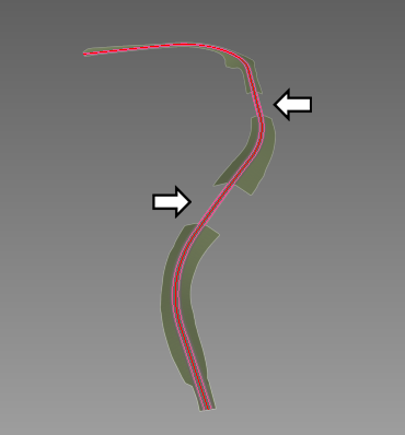
Gaps where bridges are needed
Set up the lesson:
- Continue working on your scene from the previous lesson or
 open
\civil_view\linkroad_2.max.
open
\civil_view\linkroad_2.max.
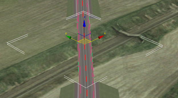
Zoom in on the area of the first bridge:
- In the navigation buttons at the lower right of the 3ds Max window, use the Field-Of-View / Zoom Region flyout to choose
 Zoom Region.
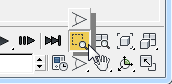
- In the viewport, drag a region to zoom in on the farther of the two gaps.
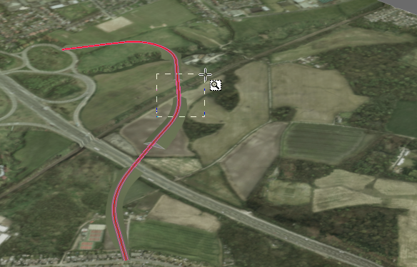
Now the viewport shows a good view of the bridge site.
Create the bridge:
- From the Civil View menu, choose Civil View
 Swept Object Style Editor.
 3ds Max opens the Swept Object Style (SOS) Editor dialog.
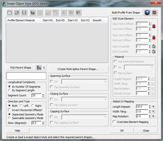
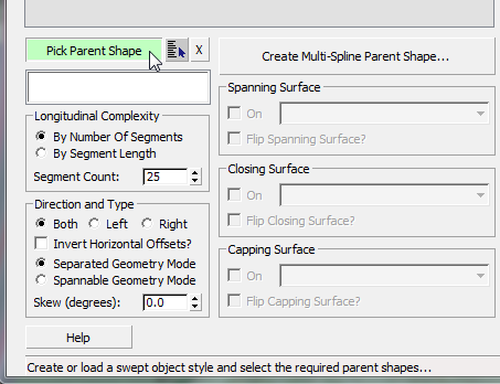
- On the SOS dialog, click to turn on Pick Parent Shape.
- In the viewport, click to select one of the segments at either side of the bridge area. The name of the shape is C3DfeatLine-Link Road-Cyclepathout - Region (2). (You might have to move the SOS dialog to see this shape clearly.)
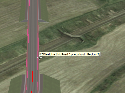
The shape you have picked consists of two splines, one on each side of the roadway where the bridge will be.
3ds Max displays a dialog that asks which mode you want to use for the swept object.
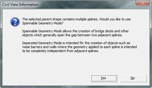
- Click Yes.
This dialog appears because the shape object contains more than one spline. In such a case, the Swept Object Style Editor can interpret the purpose of each spline in one of two ways. To generate objects such as bridge decks and tunnel linings, the Spannable Geometry Mode is desirable: This mode assumes that each spline represents either side of the road, and spanning and closing surfaces can generate "link" surfaces that span the gap between the splines. The alternative, Separated Geometry Mode, is more appropriate for creating noise barriers and retaining walls: For these kinds of features, the geometry of the swept object is applied individually to each spline in the shape.
3ds Max begins to construct the bridge.
Add curbs to the bridge:
- On the Swept Object Style (SOS) Editor, click
 (Add new element).
 After you click this, some other buttons on the toolbar become active, and the new element appears in the SOS element list.
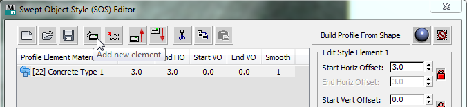
In the viewport, you can also see the new element applied to each spline.
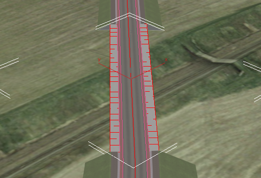
This new element will become the gutter between the main roadway and the curb.
Each element is a segment in the cross-section of the sides of the bridge. Because you chose Spannable Geometry, the elements are mirrored:
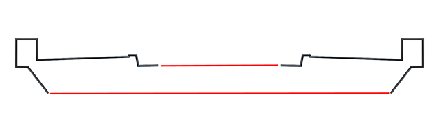
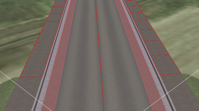
Later, you use the Spanning Surface and Closing Surface options to create the roadway at the top of the bridge, and the bridge's bottom. The diagram shows these in red. (You also set up Capping Surfaces at each end of the bridge.)
- In the Edit Style Element group, change the settings as follows:
- Start Horiz[ontal] Offset: 0.45
- Start Crossfall: –0.05
- Material ID (use the drop-down list in the Material sub-group): [6] Curb
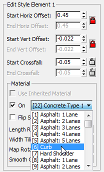 Note: Because the Horizontal and Vertical Offsets are locked, the Start Vert[ical] Offset value changes as well.
To see the effect in the viewport, it helps to
 zoom in.
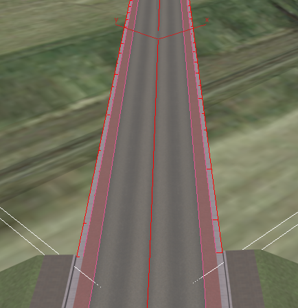
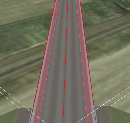
Now you can see that the width of the gutter is the same as it is on the roadway that is on the ground.
- Click (Add new element) once again.
This new element is the vertical face of the curb.
- In the Edit Style Element group, change the settings as follows:
- Start Horiz[ontal] Offset: 0.04
- Start Vert[ical] Offset: 0.225
- Material ID: [6] Curb
- Click (Add new element) once again.
This new element is the top of the curb.
- In the Edit Style Element group, change the settings as follows:
- Start Horiz[ontal] Offset: 0.15
- Start Vert[ical] Offset: 0.0
- Material ID: [6] Curb
Once again,
zooming and  panning can help you see your progress.
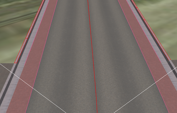
The last step in this procedure is to create a footpath outside the curb.
- Click (Add new element).
- In the Edit Style Element group, change the settings as follows:
- Start Horiz[ontal] Offset: 2.0
- Start Vert[ical] Offset: 0.05
- Material ID: [42] Paving Type 2
In addition, in the Material sub-group, set the Width Tiling value to 0.2 so the pattern of the new walkway matches the pattern of the roadway on the ground.
Do not close the Swept Object Style (SOS) Editor. You will need it in the procedures that follow.
To construct the bridge, you add new elements. As you add and refine elements, you are also creating a specific new swept object style (SOS), which you can save for use in future projects.
You have now completed the top portion of the bridge. To complete it, though, you need to add further elements so its 3D cross-section, its profile, is also complete. Once you have a complete profile, you can add surfaces that make the bridge behave and appear like a fully 3D object.
Complete the bridge profile:
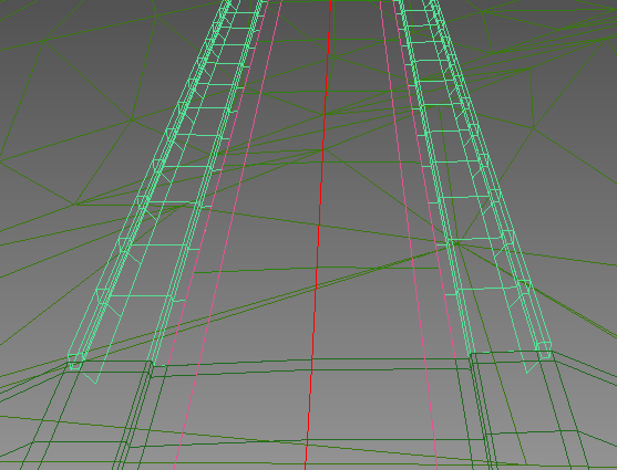
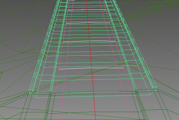
- Press F3 to change the viewport to wireframe mode.
This makes it easier to see the effects of the next steps.
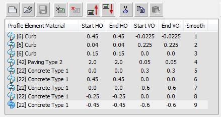
- One by one, click (Add new element) and add five new elements to the swept object style. Use the following table as a guide for the element settings.
Element number Horizontal Offset Vertical Offset Material ID 5 0.0 0.3 [22] Concrete Type 1 6 0.45 0.0 [22] Concrete Type 1 7 0.0 –0.6 [22] Concrete Type 1 8 –0.25 0.0 [22] Concrete Type 1 9 –0.45 –0.6 [22] Concrete Type 1 When you are done, the element list should show nine elements in all.
Complete the bridge surfaces:
- In the Spanning Surface, Closing Surface, and Capping Surface groups, click to turn on the On checkbox.
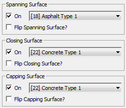
The surface material IDs should be these default values:
- Spanning Surface: [18] Asphalt Type 1
- Closing Surface and Capping Surface: [22] Concrete Type 1
3ds Max adds these surfaces to the bridge style: The spanning surface is at the top, the closing surface is at the bottom, and the capping surfaces close the ends of the structure.
- Press F3 again to turn viewport shading back on.
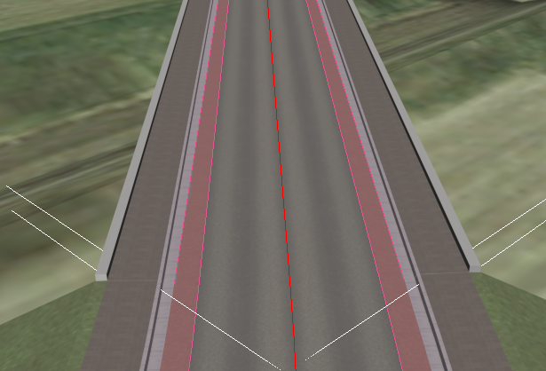
To complete the bridge, now you add surfaces to connect the two sides of the profile, and to cap the ends of the bridge.
Create the other bridge:
- Zoom out (and pan as needed) so you can see the other, nearer bridge location.
- On the Swept Object Style (SOS) Editor, click to turn on Pick Parent Shape once again.
- In the viewport, pick the shape C3DfeatLine-Link Road-Cyclepathout - Region (4). Like the shape for the first bridge, this consists of two splines, each at an outer edge of the area to be bridged.
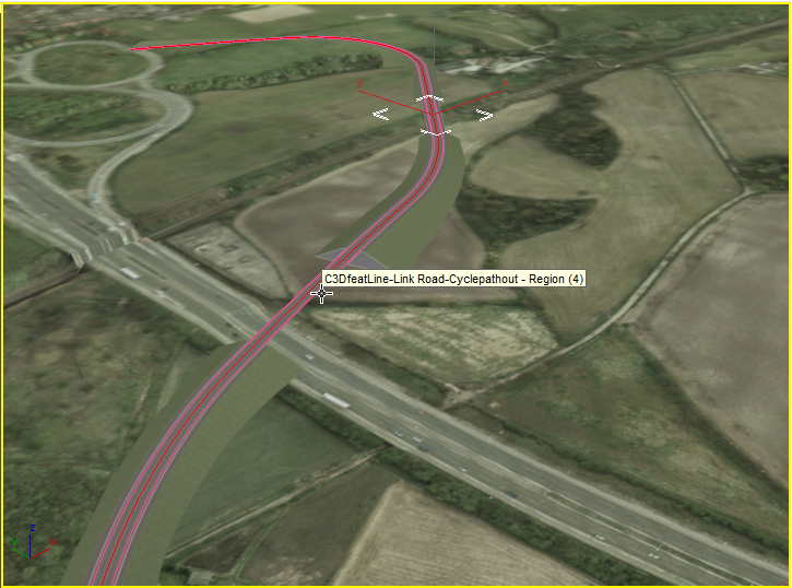
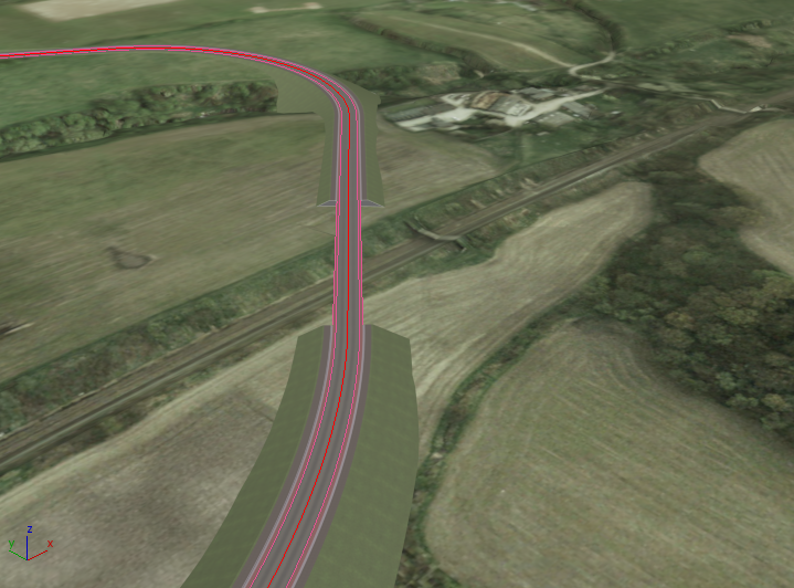
Civil View creates the second bridge in this new location.

The second bridge has the exactly the same style as the first. The only difference is that its dimensions and location are specified by the new parent shape.
Save the style:
- On the toolbar above the SOS element list, click
 (Save Style).
 - When 3ds Max prompts you, name the style myroadway_bridge.sos.
- Click OK to close the Swept Object Style (SOS) Editor.
Click Yes when 3ds Max asks if you are sure you want to close the dialog.
Save your work:
- Save the scene as my_roadway_bridges.max.