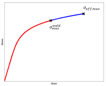
The strength reduction factor, whether calculated automatically or user-specified, is applied as a simple multiplier to scale the strength of the material. In particular, we scale the maximum effective stress, σeff,max, of the material.
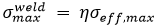
Where η is the strength reduction factor and must lie in the range 0 < η ≤ 1. This scaling of the maximum effective stress causes the material that lies on the weld surface to fail sooner than the same material that is not on the weld surface.
The strength reduction factors can be visualized in the output results with SDV12 for Abaqus and SVAR12 for ANSYS.
Automatic Calculation of Weld Surface Strength Reduction Factors
The automatic calculation of weld surface strength reduction factors is performed using the Robbins Method.

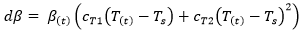

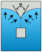
where η is the strength reduction factor calculated at each point on the weld surface. Ts represents the solidification temperature and T(t) is the temperature through time as defined in the .ws3 file. The coefficients cT1 and cT2 represent the two weld line strength coefficients associated with the Moldflow material .udb. θc is the critical angle (denoted Phi Critical in Moldflow). θ is the angle at which the converging flow fronts meet.
Before you can use the Robbins method to automatically calculate the strength reduction factors, you must provide cT1, cT2, and θc for your material. To do so, refer to the Activate Weld Surface Strength Analysis section of the User's Guide.