Use the Finishing Options area to select a finishing tool, then choose a tool clearance strategy:
- Click to Select — Click the control bar to select the tool you want to use using the Tool Database dialog. When you select the tool, click the control bar showing the name of the tool to display its parameters. To change the selected tool, click Select. To deselect the selected tool without choosing a replacement, click Deselect.
- Tool clearance strategy — Choose a clearance strategy from the list:
- Raster — Machines in passes back and forth along the X axis at a specified angle.
- Raster (Classic) — Machines in passes back and forth along the X-axis at a specified angle. This strategy creates smaller toolpath sizes, has faster calculation times and is commonly used for working with softer materials.
- Raster X & Y — Machines in two perpendicular directions at a specified angle. This strategy improves the surface finish but can be time consuming.
- Raster X & Y (Classic) — Machines in two perpendicular directions at a specified angle. This strategy creates smaller toolpath sizes, has faster calculation times and is commonly used for working with softer materials.
- Spiral — Machines in a spiral motion, stopping when the tool reaches the first edge of the composite relief. This strategy does not always allow you to machine the entire relief.
- Spiral in box — Machines in a spiral motion. When the tool reaches the first edge of the composite relief it retracts, traverses along the edge of the composite relief and then plunges to continue machining the next area of the composite relief. This strategy allows you to machine the entire composite relief, but can be time consuming.
- Spiral (Classic) — Machines in a spiral motion, stopping when the tool reaches the first edge of the composite relief. This strategy does not always allow you to machine the entire relief. This strategy creates smaller toolpath sizes, has faster calculation times and is commonly used for working with softer materials.
- Spiral in box (Classic) — Machines in a spiral motion. When the tool reaches the first edge of the composite relief it retracts, traverses along the edge of the composite relief and then plunges to continue machining the next area of the composite relief. This strategy allows you to machine the entire composite relief, but can be time consuming. This strategy creates smaller toolpath sizes, has faster calculation times and is commonly used for working with softer materials.
- Constant Z — Creates a toolpath by slicing the model at specific Z heights. This works well on near vertical surfaces which require a consistent depth of cut.
- 3D offset — This strategy is best suited to machining areas that require a constant stepover and works well on near horizontal surfaces. It creates a series of offsets starting at the outer boundary and offsetting towards the centre.
- 3D offset spiral — This strategy is similar to the 3D Offset strategy, but the toolpath cuts in a spiral motion to reduce the number of air moves made by the tool.
- Offset (Classic) — This strategy machines in repeated passes, each time moving inwards or outwards by the selected tool's Stepover value. You can see the stepover value of the selected tool when its machining parameters are displayed.
Note: The availability of some strategies is license dependent and is dependent on the option you select in the Area to Machine area of the panel. - Angle — Enter the angle from the X axis at which you want the tool to move.
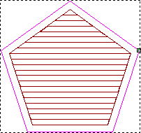
Raster angle of 0
 ...
...
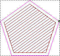
Raster angle of 36
...
 Tip: You can set the default raster angle using the Options panel.Note: This setting is available only when you select Raster, Raster (Classic), Raster X & Y, or Raster X &Y (Classic).
 - Start inside/outside — Choose whether to start offsetting from the inside or the outside of the clearance area.
Note: This setting is available only when you select 3D offset or 3D offset spiral.
- Surface links — Select this option to set a threshold for the surface links. If a link is above the threshold, the toolpath safely retracts to Safe-Z; but if the link length is below the threshold, the tool link moves across the model surface to the next offset or slice.
Note: This setting is available only when you select Constant Z, 3D offset, or 3D offset spiral.
- Cutting direction — Select a cut direction:
- Both — Select the option to cut back and forth across the model, which reduces the number of air moves made by the tool.
- Climb — Select the option to rotate the cutter in the same direction as the feed motion. The option is selected by default.
- Conventional — Select the option to rotate the cutter in the opposite direction to the feed motion.
Note: This setting is available only when you select 3D offset or 3D offset spiral. - Tolerance — Enter a value to determine how closely the shapes of any Bézier curves are followed. Entering excessively small values for this tolerance increases toolpath files sizes and slows down calculation and machining times.
- Allowance — Enter a value to give an offset above the relief for your machining.
- Multiple Z passes — With the
Raster (Classic) or
Offset (Classic) toolpath, you do not have separate roughing and finishing toolpaths. Instead, all the material is removed with one tool. If you want to remove the material in a series of passes, click the control bar to expand the
Multiple Z Passes area and select
Do Multiple Z Passes. For each pass, the tool moves downwards by its
Stepdown value. You can see the stepdown value of the selected tool when its machining parameters are displayed. The
Stepdown
value of the tool determines the number of passes made between the first and last pass in the toolpath.
- Start Z — Enter the Z height of the first machining pass.
- Finish Z — Enter the Z height of the last machining pass.
Note: This setting is available only when you select Raster (Classic) or Offset (Classic).