To Create a Feature Control Frame and Align to a Diameter Dimension (AutoCAD Mechanical)
Click
Annotate tab
Symbols panel
Feature Control Frame
.
Find
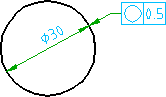
Click the circle to attach the symbol to.
Enter P to redefine the start point.
Move the cross hairs towards the dimension line until the leader snaps to the intersection of the dimension line and circle, and then click.
Press ENTER.
In the Feature Control Frame dialog box, enter the data.
Click OK.
Related Concepts
About Creating Feature Control Frame Symbols (AutoCAD Mechanical)
About Editing Feature Control Frame Symbols (AutoCAD Mechanical)
Related Tasks
To Create a Feature Control Frame Symbol (AutoCAD Mechanical)
To Create a Feature Control Frame Symbol, Using the Symbol Library (AutoCAD Mechanical)
To Create a Feature Control Frame Symbol With a Surface Indication Leader (AutoCAD Mechanical)
To Create a Feature Control Frame and Align to Dimension Text (AutoCAD Mechanical)
To Create a Feature Control Frame and Align to the Horizontal Landing of a Dimension
To Create a Feature Control Frame and Align to a Linear Dimension (AutoCAD Mechanical)
To Change the Toggle Symbol Leader Orthogonal Mode Key (AutoCAD Mechanical)
To Add a Secondary Leader to a Feature Control Frame Symbol (AutoCAD Mechanical)
Related Reference
Commands for Working With Symbols (AutoCAD Mechanical)