Note: This operation is typically supported by the ANSI standard (or any dimension style is configured to use a “Centered vertical text placement).
- Click
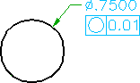
 Feature Control Frame. Find
 - Click near the dimension text, at the approximate position the left middle of the feature control frame must appear.
- Press ENTER.
- In the Feature Control Frame dialog box, enter the data.
- Click the Leader and Text tab.
- Click Attach. The dialog box hides.
- Click the dimension text. The dialog box displays again.
- Click OK.