- Import a model.
- Restructure the assembly.
- Convert models to assets.
Step1: Importing a Model
- Start Inventor and click New Layout on the Factory tab.
- Select Insert Model from the Layout drop-down menu on the Factory ribbon and locate the assembly file.
- Verify the model position making sure it is in the desired location on the Z-axis. Typically the machine base will sit on the floor.
- Right-click, and select
Done to place the model.
If you need to make further adjustments, click Set Landing Surface to select the face to place on the floor, and then click Done.
If the original model has a pre-defined insertion point, you can view the defined coordinates and change the current coordinates to match. Right-click on the model in the Model browser, select iProperties, and then click the Occurrence tab.Note: The Z Offset represents the landing surface you selected, so should not need to change.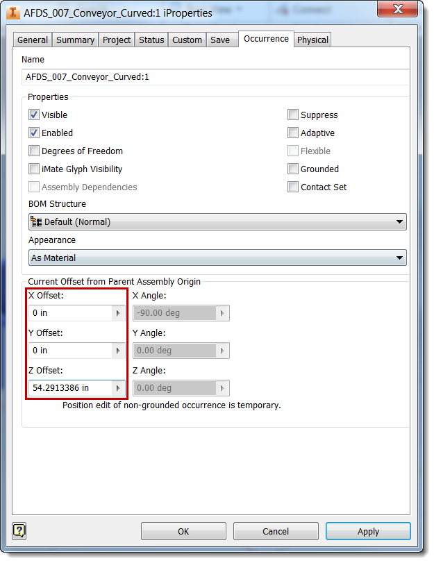
- Click the Save icon at the top of the window or press Ctrl+S to save the file.
Step 2: Restructuring the Assembly
- Click
+ next to the imported assembly in the
Model browser.
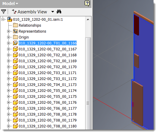
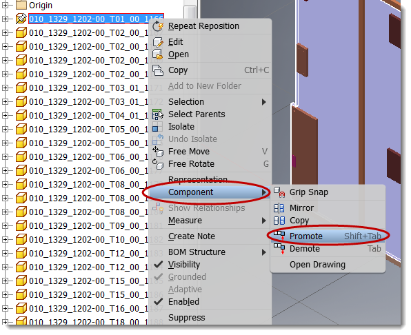
- Locate an item to convert to an asset. Right-click, select
Component, and then select
Promote.
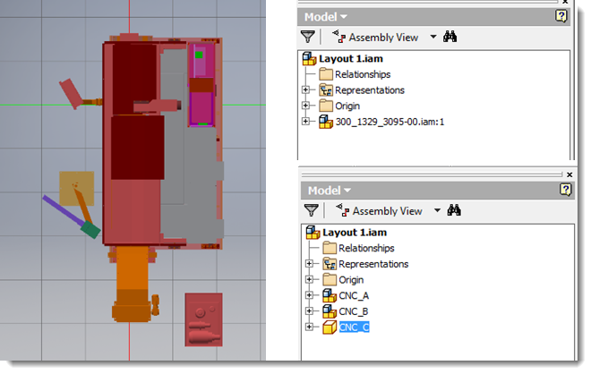
The message "The restructure operation may result in lost features..." appears. Select Yes to continue.Note: You can also drag and drop items in the browser to rearrange and group models together. - Repeat step 2 until all items are structured as desired. In this example, the file is restructured to convert three items (CNC_A, CNC_B, CNC_C) to assets and to maintain their relationship.
- Click the Save icon at the top of the window or press Ctrl+S to save the file.
Turning off assembly detail (optional)
- Locate an assembly in the Model browser, right-click, and select Open.
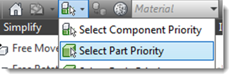
- From the menu bar, change the selection priority to
Select Part Priority.
- In the model, locate an item for which you want to turn off visibility.
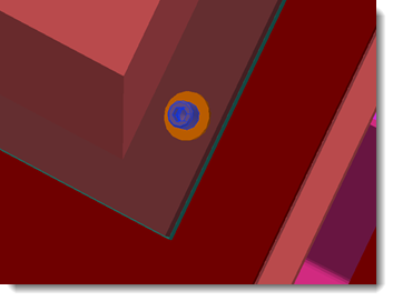
- Select the item, right-click, and choose Selection > Component Size. The size of the selected part is used to search through the model and highlight all same-sized or smaller items. Change the size in the dialog to adjust the selection criteria, and then click the green check mark to start the search.
- Right-click on a highlighted item and select Suppress to hide it from view. The item appears crossed out in the browser.
- Click the Save icon at the top of the window or press Ctrl+S to save the file.
Setting Convert Options
The Convert to Asset command uses a shrinkwrap feature to simplify files. Properly configuring the simplification options is critical for successfully creating lightweight models. You can configure simplification settings from the Asset Builder tab in Factory Options.
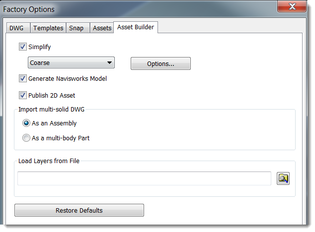
Medium and Coarse options automatically appear in the drop-down list. Custom options might also appear and are defined in the User App Data folder (%AppData%\Autodesk\Factory Design 2018\Simplification\). Click options to enter additional simplification settings.
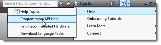
- Highlight Help in the Inventor ? drop-down menu.
- Select
Programming/API Help.
- Search for DerivedAssemblyDefinitionObject.
Step 3: Converting Models to Assets
Now you are set to create the assets. For step by step details see Converting Assembly Components to Assets.