Anisotropic materials for inserts in injection overmolded parts expands the scope of material choice from traditional isotropic metals and transversely isotropic plastics to emerging new materials such as fiber reinforced composites. These new materials can provide a significant reduction in product weight and environmental costs.
There are many forms of general anisotropic materials, such as pultruded rods, woven mats and unidirectional tapes. Each of these materials consists of reinforcing fibers and a base matrix material, such as a thermoplastic or thermosets material. In most cases, it is likely that the fibers embedded in the composite component are strongly oriented. As fibers normally have very different physical properties from the matrix materials, the fiber orientation introduces significant anisotropy in the thermo-mechanical properties of the composite fiber-matrix system. As a result, multiple parameters are required to define an anisotropic material. The user-defined material formulation is extended to full anisotropy in order to account for complex material structures that do not necessarily have any planes of symmetry.
This feature is supported by the following mesh types:
 3D
3D
and for the following thermoplastic injection molding analysis sequences:
- Core shift analysis, where the core elements are assigned the property Core (3D).
- Warp analysis, where the part insert elements are assigned the property Part insert (3D).
User defined material inputs
For a fully anisotropic material without any plane of symmetry, such as occurs with combinations of multiple fiber sheets with random alignment angles, all 21 of the elastic constants are independent of each other, and potentially non-zero. To define your own anisotropic material for the simulation, you need to provide all 21 of the independent elastic stiffness constants.
The coefficient of thermal expansion (CTE) for a fully anisotropic material can be different in all three principal directions and three shear directions. As a result, you also need to provide values for the 6 coefficients of thermal expansion.
Local axes
An injection overmolded design can involve fiber reinforced composite inserts of very complex geometries and double curved surfaces, such as from a thermoforming or draping process. As a result, the fiber sheet direction, and thus the composite principal directions, vary according to the insert surface normal and any in-plane shear which has occurred during forming. For accurate simulation, it is critical that you define the local material axes correctly in the Anisotropic properties dialog. You input the vectors for the first and second local axes, and Insight automatically calculates the third local axis. The first and second local axes must be orthogonal to each other.
To enter your own anisotropic material data:
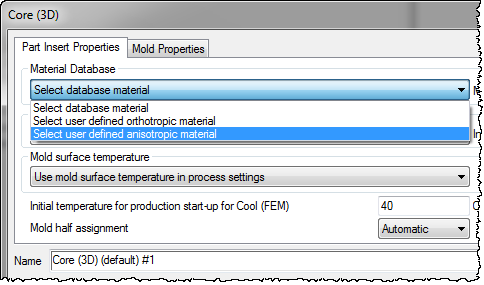
- Right-click the Part insert (3D) or Core (3D) elements, and select Properties.
- Choose
Select user-defined anisotropic material from the drop down menu associated with
Material Database.
- Click User-defined anisotropic properties to open the Anisotropic property dialog.
- Enter values for all 21 elastic constants and 6 coefficients of thermal expansion.
- Enter values to define the first and second local axes.
- For a core shift analysis, ensure that the Perform core shift analysis option is selected.
- For a warp analysis, ensure that your analysis sequence includes a Warp analysis.
- Once you have run the analysis, check the deflection results to see the effect of the anisotropic material properties.