Gas-assisted Injection Molding
This process begins with a partial or full injection of polymer melt into the mold cavity. A compressed inert gas, usually nitrogen, is then injected into the core of the hot polymer. It drives the polymer into the mold until it is filled. After the filling phase, the gas driven packing and cooling phase commences before part ejection.
This process requires lower tonnage injection molding machines, less material, and shorter cycle times. It can also result in less residual stresses in the part, with the potential of sink marks being reduced. Finally it reduces part warpage, with the overall quality and dimensional stability of the part greatly improved.
However, as the temperature of the mold and the gas bubble are dependent and interact with each other, this Gas-assisted Injection Molding process can be unstable. For that reason, the temperature coupling between the gas flow solution and the cooling analysis in the mold should be strong, to ensure an accurate simulation for all cases.
To access the 3D Cool analysis for Gas-assisted Injection:
- Set a
Gas-assisted Injection Molding analysis for your 3D model, by clicking
 () and select
Gas-assisted Injection Molding from the list.
() and select
Gas-assisted Injection Molding from the list.
- Click
 ().
().
There are two new types of Analysis Sequences:
- Four new sequences beginning with Cool (FEM): Cool (FEM), Cool (FEM) + Fill, ...
- Two new sequences having Cool (FEM) in the middle of the sequence: Fill + Pack + Cool (FEM) + Fill + Pack and Fill + Pack + Cool (FEM) + Fill + Pack + Warp.
Sequences beginning with Cool (FEM)
The four new sequences beginning with Cool (FEM) work with the Flow analysis on every iteration option within the Cool (FEM) Solver Parameters dialog.
To access this dialog, click
 (). Then click
Next until the
Cool (FEM) Settings page appears. Finally click
Cool (FEM) Solver Parameters....
(). Then click
Next until the
Cool (FEM) Settings page appears. Finally click
Cool (FEM) Solver Parameters....
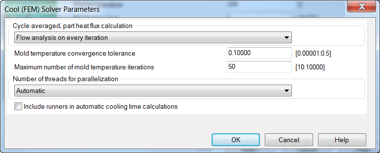
Figure 1: Cool (FEM) Solver parameter showing Flow analysis on every iteration option
The Flow analysis on every iteration solution provides, in theory, the most accurate solution for gas Cool, however it is slow, especially if the process is unstable.
Using the Conduction solver
An option using the Conduction solver for gas assisted injection molding has been added, resulting in a much faster solution. However this solution may not be as accurate as the Flow analysis on every iteration option.
The conduction solver assumes that the part is full of molten polymer at melt temperature at the start of the cycle. So this second approach needs one of the following sequences to be set: Fill + Pack + Cool (FEM) + Fill + Pack or Fill + Pack + Cool (FEM) + Fill + Pack + Warp.
The sequence begins with a preliminary Gas-assisted Fill + Pack analysis with a constant mold temperature. This analysis captures the approximate shape and position of the gas core in the part. The conduction solver of the Cool solution uses this gas core to calculate the mold wall temperatures. These mold wall temperatures are then used in a subsequent Flow analysis and a new gas core is calculated. This final flow analysis with its gas core provides the final solution.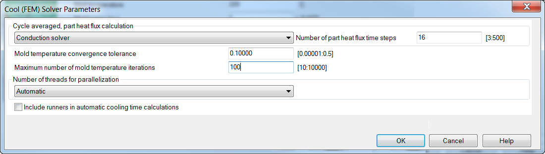
Ensure that the first and second gas-assisted flow analysis results are similar regarding the gas core. If the two analyses have vastly different shaped cores then the results may be inaccurate. In this case we recommend using Flow analysis on every iteration methodology.