Cool (FEM) is a new analysis that has been added to the Thermoplastics Overmolding molding process.
Cool (FEM) for two-shot sequential overmolding is supported for the following mesh types:
 3D
3D
and for the following Cool (FEM) options:
- Averaged within cycle
- In cycle transient
- Production startup
Model components
To run a Cool (FEM) analysis in thermoplastics overmolding, all 10 mold and model components in the image are supported. The stationary platen (1) includes an optional feed system for the first component and another optional feed system for the second component. If feed systems are modeled, the Cool (FEM) analysis requires, in addition, a copy of the feed system for the first component modeled into the 2nd component position (6) .
Modeling components required in a Cool (FEM) analysis in thermoplastics overmolding

Key: 1. Stationary platen, 2. Rotating platen, 3. First shot part component, 4. Overmolded part component, 5. First component feed system, 6. Overmolding component feed system, 7. Second shot part component, 8. Second shot feed system, 9. Cooling channels in stationary platen, 10. Cooling channels in rotating platen
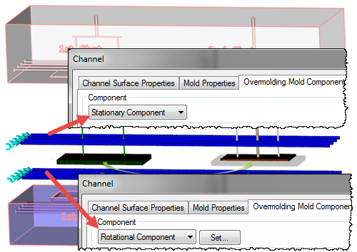
Mold platen assignments
Both cavities are filled simultaneously during a cycle. The mold then opens to eject the finished component, and the rotating platen rotates by 180 degrees to place the 1st component into position for the overmolding injection. To identify the rotating platen, assign the property Rotational Component to the associated cooling channels. Assign the property Stationary Component to the cooling channels of the stationary platen. When one complete cycle is finished and the mold opens, the final temperature from the first shot mesh is used as an initial condition for the overmolded mesh.
Fore more information ont his process see Cool (FEM) analysis in two-shot sequential overmolding.
Analysis setup
The analysis setup is similar to other thermoplastic overmolding analyses, with one major difference. All the elements of the first shot components (3) and (5), that form the basis of the overmolded insert for the second shot, must be assigned the Rotation element property.
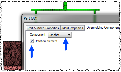
For second shot components (7) and (8), leave the Rotation element option unchecked.
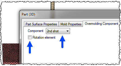
The overmolded component elements (4) and (6), in the second shot cavity, are assigned the properties 1st shot and Rotation element is left unchecked.

Following the Cool (FEM) analysis, the flow analysis is solved on the components in the second shot cavity, and all elements in the first cavity marked as Rotation elements are ignored.
For more information on how to set up a Cool (FEM) analysis for two-shot overmolding, see Prerequisite Setup Tasks for a Cool (FEM) analysis
Cool results
Mold temperature results show the temperature distribution for an entire molding cycle, from injection into the first cavity to ejection from the second cavity. In this mold temperature result, the mold node is on the mold/ 1st shot cavity boundary and the mold is rotated 180 into the 2nd shot overmolding position. The result shows the mold temperature decreases as the overmolded component is injected, because the node location is insulated from the 2nd shot melt by the 1st component. The part is then ejected, and at 35 seconds, the platen rotates so the node is back in the 1st shot position. When the 1st shot is injected into the cavity, the mold temperature at the node increases drastically, then cools again over the course of the cycle. This mold temperature history is used as the temperature boundary condition for subsequent flow and overmolding flow analyses to provide more accurate solutions.
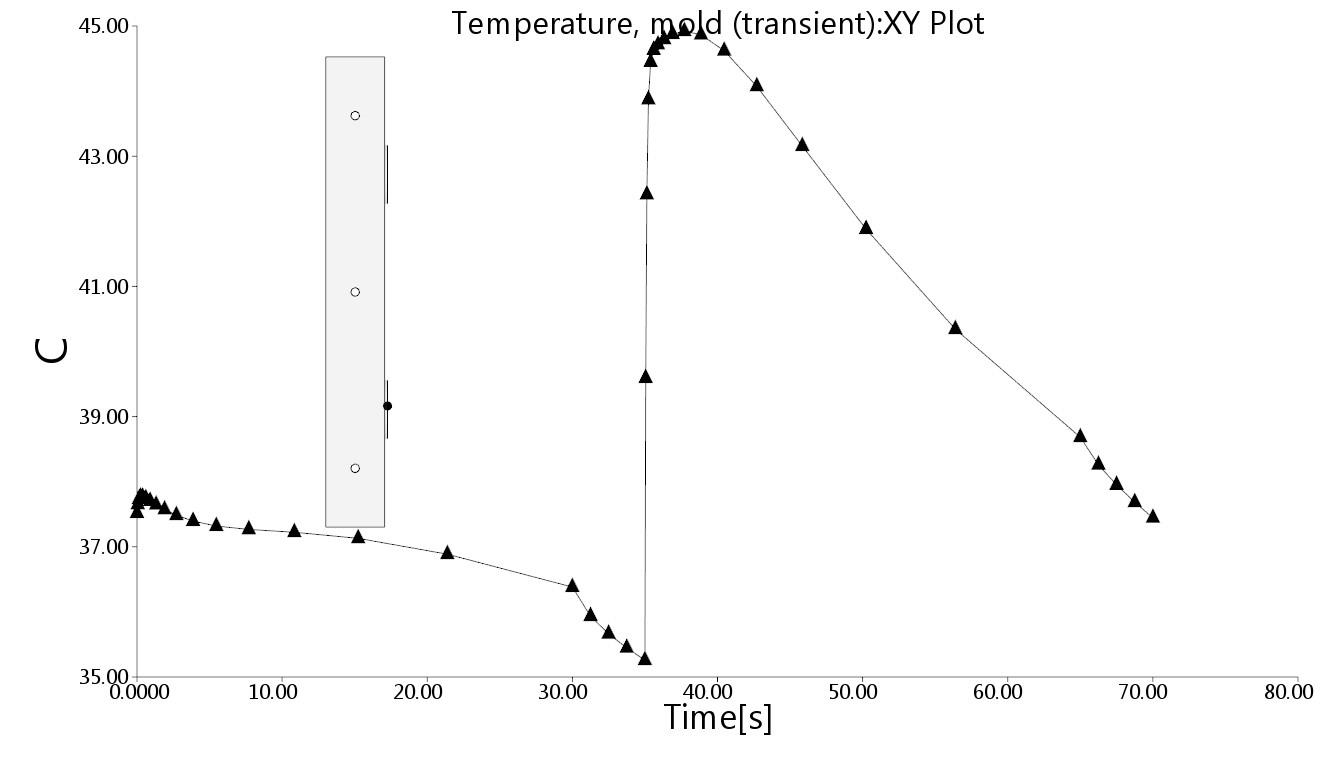
Mold temperature result
For more information on overmolding results, see Interpreting the results of a two-shot overmolding Analysis