The Relation type determines the relationship between the attachments on the two components in the assembly.
There are three options:
- Coincident

- Angular/Parallel

- Perpendicular

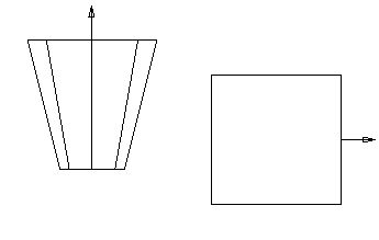
In the 2D example below:
 is the master component
 is the slave component
 shows the selected plane attachments
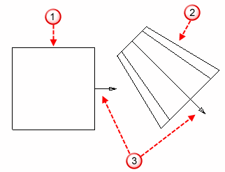
The slave component is positioned using the attachment of the master component.
In the example, the master has a plane attachment. The plane of the attachment is used to position the slave component. The line representing the plane is indicated by  :
:
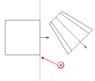
Coincident - The slave is positioned so that its attachment is coincident with the attachment of the master.
In the example, the slave is positioned so that its plane attachment lies in the same plane as that of the master.
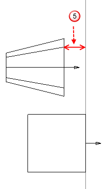
You can position the slave such that its attachment is at a distance from the attachment of the master. Enter a Distance or use the Angle/distance scaler to define a distance.
In the example, the slave is positioned so that its plane attachment is at a distance from the plane attachment of the master. The distance is indicated by  :
:
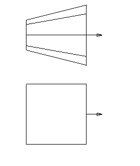
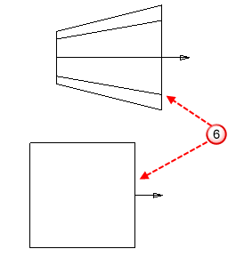
Angular/Parallel - The slave is positioned such that its attachment is at an angle to the attachment of the master. If the angle is 0, the slave is positioned so that its attachment is parallel to the attachment of the master. Enter an Angle or use the Angle/distance scaler to define an angle.
In the example, the slave is positioned so that its plane attachment is parallel to the plane attachment of the master. The position of the two parallel planes is indicated by  .
.
Angular/Parallel relation type may be set for the following types of relations:
- plane to plane
- plane to line
- line to plane
- line to line
The distance between the planes is undefined at this stage and must be specified by another relation type.
Perpendicular - The slave is positioned such that its attachment is perpendicular to the attachment of the master.
In the example, the slave is positioned so that its plane attachment is perpendicular to the plane attachment of the master.