Use the Create Relation dialog to create relations between components by selecting attachments. In this example, a relation is created between two solid block components:
- Click Assembly tab > Modify panel > Attachment to display the
Create Relation dialog:
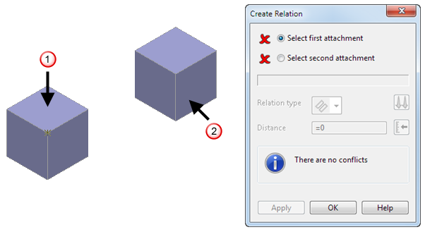
- In the graphics window, select the first attachment on the first component. For example, select the top plane
 .
.
This is the master component.
- Select the second attachment on the second component. For example, select the right-hand plane
 . This is the slave component.
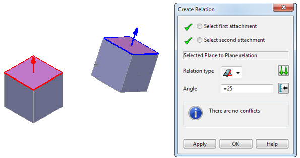
The second component is rotated, so that the selected plane attachments align. Selected Plane to Plane relationis displayed in the dialog and
 is displayed as the
Relation type.
Note: Relations are added to the assembly tree when the second attachment is selected. If you make an incorrect selection before you click Apply, click the Select first attachment or Select second attachment option so that
is displayed as the
Relation type.
Note: Relations are added to the assembly tree when the second attachment is selected. If you make an incorrect selection before you click Apply, click the Select first attachment or Select second attachment option so that is displayed, and reselect the attachments in the graphics window.
- Use the dialog to specify the relation between the components. For example:
- Select
 from the
Relation type drop-down list to change the relation type to
Angular.
from the
Relation type drop-down list to change the relation type to
Angular.
- Toggle
 to specify the orientation of the slave attachment with the master attachment. Choose from:
Align — the slave attachment lies in the same direction as the master's.
Anti-align — the slave attachment lies in the opposite direction to the master's.
- Enter a
Distance
of
25,
or click
 and use the slider in the
Angle/Distance Scaler dialog to specify the angle distance.
and use the slider in the
Angle/Distance Scaler dialog to specify the angle distance.
- Click
Apply. The model is updated:
The dialog remains open to allow you to specify additional relations.
- Select
- Click
OK
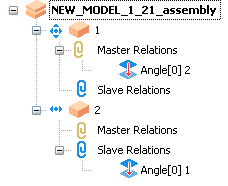
to finish creating relations. The created relationship is added to the assembly tree: