You can define a family of electrodes from one electrode. This family is used to spark different stages of the same region. The different stages possible are rough, semi, and finish:
- The electrode for the rough stage burns away most of the material from the region.
- The electrode for the semi stage removes more material from the region to give a smoother finish.
- The electrode for the finish stage burns the final bits of material from the region. It gives the best finish on the surface.
Use the Electrode Wizard - Design page to define the electrode family, as detailed below:
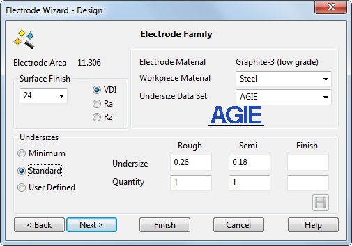
Electrode Area — This is the surface area of the electrode. It is automatically calculated by PowerShape.
- Surface Finish — Specify the value required for the end finish by:
- Selecting a value from the drop-down list. The available values are determined by the selected Undersize Data Set.
- Entering a custom value. This selects the User defined undersizes option.
As a rough guide, the lower the value, the smoother the finish.
VDI/Ra/Rz — Select the units of the surface finish. The units available reflect the Undersize Data Set selected.
- Electrode Material — Material used by the electrode. If you want to associate custom material names with one of the internal materials of Electrode, you can add the materials to the Electrode alias file.
- Workpiece Material — Select a different workpiece material. The list displayed reflects the Undersize Data Set selected.
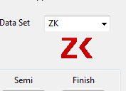
- Undersize Data Set — Select the default data set to be used for electrode undersizes. The logo of the currently selected option is displayed below the list.
 Note: Use the electrode_undersizes.con file to control the undersize data sets that are available in the wizard. The file is installed in:
C:\Program Files\Autodesk\PowerShapexxxxx\file\electrode
where xxxxx is the version number of PowerShape and C is the disk on which PowerShape is installed.
You can edit the configuration file to suppress competitors' logos and datasets. Instructions for customising the configuration are included in the file. By default, all datasets are included in the Undersize Data Set list and the logo of the selected data set is displayed.
Note: The MPP undersize data set is only displayed if the +GF+ MPP software is installed on your computer. If using the MPP option, copy the following files (from the path above) to the shareddb:- mpp_workpiece_materials.txt — check this file contains the same list of workpiece materials as the MPP system.
- mpp_interface.con — modify this file to configure the connection between PowerShape and MPP.
- Undersizes — This section sets the undersize
 for each electrode in the family, as shown below:
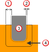 Undersize
 Spark gap
 Electrode
 Material to be removed
Select the option you require:
Note: The Electrode Wizard will only display undersize options that are suitable for use with the current electrode. If no suitable default options are available, the User defined option is selected automatically.Minimum — The recommended undersize values for the Rough, Semi, and Finish electrodes are automatically inserted. These values are provided by the manufacturer. Use this option to preserve sharp corners.
Standard — The recommended undersize values for the Rough, Semi, and Finish electrodes are automatically inserted. These values are provided by AGIE.
User Defined — Select this option to enter your own values. To save undersize values for future use:- Select User Defined and enter the appropriate Undersize and Quantity.
- Click
Save.
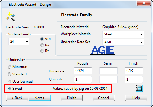
The Saved option is automatically selected, together with information about who saved the information and when it was saved.
When you next create an electrode with the same settings (burn area, material, surface finish), the saved settings are used by default.
Tip: If you do not want to define a family of electrodes, select User Defined and do not enter any values.
The recommended undersizes depend on the material: Copper, Graphite-1, and Graphite-2 have different undersizes for the same Surface Finish value; Graphite-2 and Graphite-3 have the same undersizes.
Note: Only one electrode is created in the model when a family is defined. The undersize values for the family can be transferred to PowerMill. It is then used to create the different toolpaths from the same electrode. - Quantity — Enter the quantity required for each family member. These quantities are used in the setup sheet and in the exported HTML.
- Next — Displays the Export Options page of the Electrode Wizard - Design.