When a side-sparking or vector-burn electrode is created, the vector information is included in the GA Setup Sheet.
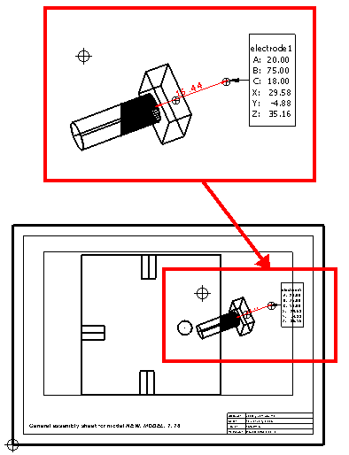
A, B, C — The rotation that defines the burn vector.
X, Y, Z — The point where the electrode changes from Z motion to moving in along the burn vector.